UPM3 HYBRID 25-70 130
Installation and Operation Manual
Grundfos UPM3 HYBRID 25-70 130 mm Pump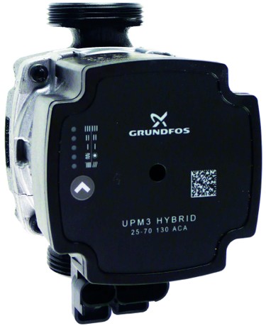
Contents
Design
Wet-running circulation pump with G 6/4” M connection.
| Electrical Data | |
| Power supply | 230 V, 50 Hz |
| Power consumption (min./max.) | 2/52W |
| Current (min./max.) | 0.04/0.52 A |
| IP rating | IP44 |
| Max. speed | 5766 rpm |
| Weighted average power | ≤ 25 W |
| Energy Efficiency Index | ≤ 0.20 by EN 16 297/3 |
| Motor protection | not needed |

| Minimum pressure at pump suction port | |
| Minimum pressure at suction port to avoid cavitation | 0.5 mH₂ O at 75 °C |
| 5.0 mH₂ O at 95 °C | |
| 10.8 mH₂ O at 110 °C | |
Pump Control
The circulation pump can be controlled:
- internally without a PWM signal by selecting a suitable mode and pump performance curve
- by an external PWM A control signal (profile for use in heating systems) or PWM C control signal (profile for use in solar thermal systems)
Performance Curves
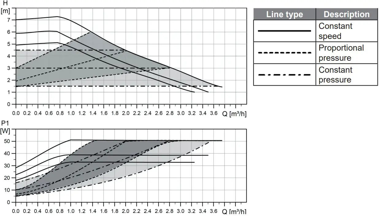
Description of Pump Frofiles
a) INTERNAL CONTROL – Proportional pressure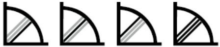
- Head (pressure): reduced with growing system pressure drop and increased with sinking system pressure drop (typically e.g. opening / closing of thermostatic heads)
- Pump operating point: moves up or down on the selected proportional pressure curve depending on the current system pressure drop.
| CONTROL MODE | DESCRIPTION | |
| Proportional pressure | I | The lowest curve of proportional pressure |
| II | The middle curve of proportional pressure | |
| III | The highest curve of proportional pressure | |
| AUTO | Automatically controls performance in the range from the Automatically highest to the lowest proportional pressure curve | |
b) INTERNAL CONTROL – Constant pressure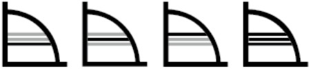
- Head (pressure): kept constant, disregarded of the system pressure drop
- Pump operating point: moves on the selected constant pressure curve depending on the current system pressure drop.
| CONTROL MODE | DESCRIPTION | |
| Constant pressure | I | The lowest curve of constant pressure |
| II | The middle curve of constant pressure | |
| III | The highest curve of constant pressure | |
| AUTO | Automatically controls performance in the range from the highest to the lowest constant pressure curve | |
c) INTERNAL CONTROL – Constant speed
- The pump runs at constant speed.
- Pump operating point: moves up or down on the selected constant curve depending on the current system pressure drop.
| CONTROL MODE | Max. H (upper graph) | Max. P1 (lower graph) | |
|
Constant speed |
I | 5 m | 33 W |
| II | 6 m | 39 W | |
| III | 7 m | 52 W | |
d) EXTERNAL CONTROL – PWM C (solar)

- The pump runs on a curve of constant speed depending on the current PWM value.
- The speed will increase with the increase of the PWM value. If PWM equals 0, the pump stops.
e) EXTERNAL CONTROL – PWM A (heating)

- The pump runs on a curve of constant speed depending on the current PWM value.
- The speed slows down when the PWM value rises. If PWM equals 0, the pump runs at its max. speed.
| CONTROL MODE | Max. H (upper graph) | |
|
PWM A |
I | 5 m |
| II | 6 m | |
| III | 7 m | |
Settings Display
DISPLAY – LED MARKING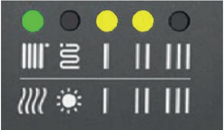 The LED marking is further omitted for better clarity.
| DISPLAY | CONTROL MODE | ||
| green LED NOT FLASHING | INTERNAL | ||
| 1 |  |
Proportional pressure AUTOADAPT | |
| 2 |  |
Constant pressure AUTOADAPT | |
| 3 |  |
Proportional pressure | I |
| 4 |  |
II | |
| 5 |  |
III | |
| 6 |  |
Constant pressure | I |
| 7 |  |
II | |
| 8 |  |
III | |
| 9 |  |
Constant speed | I |
| 10 |  |
II | |
| 11 |  |
III | |
| 12 |  |
PWM C | |
| 13 | PWM A | I | |
| 14 | II | ||
| 15 | III | ||
| GREEN LEDS FLASHING FREQUENCY | CONTROL | PWM SIGNAL RECEPTION |
| Not flashing | Internal | – |
| 1 flash per second | External | NO |
| 12 flashes per second | External | YES |
WARNING: LEDs may be turned by 90° or 180°, or mirrored, depending on the specific pump type.
When switched on, the pump runs at factory settings or the last setting. The display shows the current pump performance.
Setting selection
To select your desired setting, press the button repeatedly until you find the setting you need (see the table above). If you pass the desired setting, you have to go one more round until it appears again. The order of modes corresponds to the table.
Error display
| DISPLAY | CONTROL MODE |
| Seized pump | |
| Too low power supply voltage | |
| Electric fault |
Prohibited pump positionsPermissible pump positions
Pump wiring
©2022 We reserve the right to errors, changes and improvements without prior notice.
v1.0-03/2022
REGULUS spol. s r.o.
E-mail: [email protected]
Web: www.regulus.eu![]() www.regulus.eu
www.regulus.eu