Front Runner KSTF001 Slimsport Roof Rack Instruction Manual
aspects of your warranty. Before you begin, take a moment and open all your Front Runner rack kit boxes and gather the assembly instructions for the various components.
- A Front Runner Mounting system specific to your vehicle
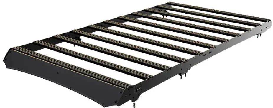
- A Front Runner Rack Tray or Load bar Slats
GET ORGANIZED
| 1 | 2X | Foot Rail Front LH / RH |
| 2 | 2X | Foot Rail Rear LH / RH |
| 3 | 2X | Stiffener Plate 01 |
| 4 | 2X | Stiffener Plate 02 |
| 5 | 2X | Stiffener Plate 03 |
| 6 | 2X | Splice Plate |
| 7 | 11X | Slimsport Slat |
| 8 | 44X | M6 x 25 Thread Forming Screw |
| 9 | 20 X | M6 x 16 Flange Button Head |
| 10 | 20 X | M6 Nyloc Nut |
| 11 | 22 X | M6 Nut Cap |
| 12 | 8X | 10mm Plastic Spacer |
| 13 | 8X | M8 x 19 x 12 Flat Washer |
| 14 | 8X | M8 Spring Washer |
| 15 | 2X | M6 x 12 x 1 Flat Washer |
| 16 | 2X | M6 Spring Washer |
| 17 | 2X | M6 x 30 Hex Bolt |
| 18 | 8X | M8 x 60 Hex Bolt |
| 19 | 3X | Jack Nut Long |
| 20 | 1X | Jack Nut Tool |
| 21 | 2X | M6 x 30 Button Head |
| 22 | 8X | M8 Nut Cap2 |
TOOLS NEEDED
- 13mm 10mm
- Anti Seize / Oil
- Measurement Tap
- Cordless Driver
- Sealant
- Marker
- Torx T30

- 5mm 12mm
- Insulation Tape
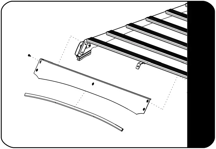
FIGURE 1.1
ASSEMBLY
Secure the Splice Plates (Item 6) to the Foot Rails (Items 1 & 2) as shown using M6 x 16 Flange Button Head Bolts and M6 Nyloc Nuts (Items 9 & 10). Secure the Stiffener Plates (Items 3, 4, & 5) to the Foot Rails (Items 1 & 2) using M6 x 16 Flange Button Head Bolts and M6 Nyloc Nuts (Items 9 & 10) Do this to both LH & RH Foot Rails. Place M6 Nut Caps (Item 11) over all Nyloc Nuts.
 Fit 10 Slimsport Slats (Item 7) to assembly 2.1 using M6 x 25 Thread Forming Screws (Item 8).
Note do not fit front slat.
Apply a little Anti Seize / oil on screw threads before inserting. Note these are thread forming screws.
Tightening Torque 8-10Nm / 5.9 ft lb – 7.38 ft lb. Take care when using a cordless driver.
PREPERATION
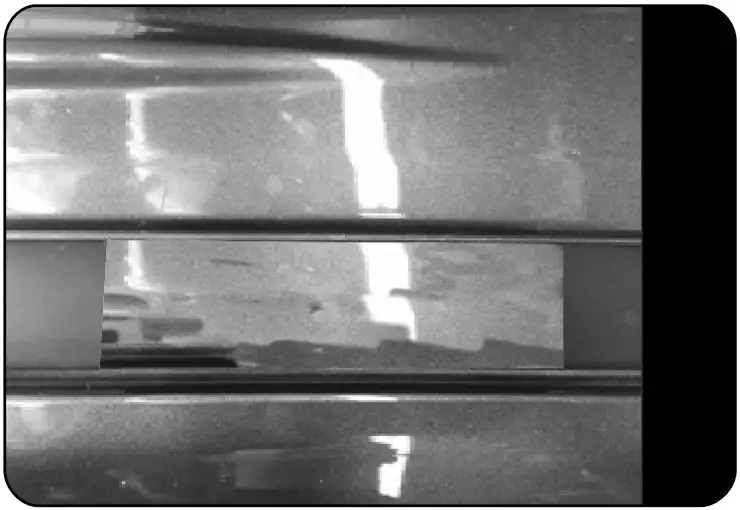
With the factory rails removed and starting at the front edge of the molding, measure and mark the dimensions as shown onto both the LH & RH ditch moldings.
PREPERATION
PERMANENT FITMENT (RECOMMENDED
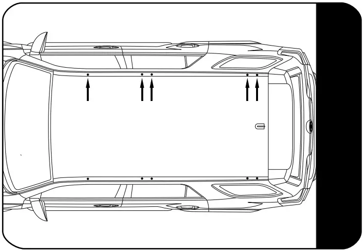
Place the assembled Rack on the vehicle, lining up the holes in the foot rail with the factory holes in the roof. Mark the hole centres where the ditch moldings were cut out. Remove the Rack.
Before drilling the holes in the roof, take both the 5mm & 12mm drill bits and wrap a band of insulation tape around each bit to act as a stopper to prevent you from drilling to deep as there are airbags located below where you will be drilling. Drill a 5mm pilot hole on both markings. Open holes to 12mm.
Insert the M6 Button Head Bolt (Item 21) into the one side of the Installer Wrench (Item 20), loosly fit a Jack Nut (Item 19) to the Button Head Bolt as shown. Using the Installer Wrench and a M6 x 30 Button Head Bolt, insert the M6 Jack Nuts into the holes drilled. Place the Assembly into the holes drilled in 3.3. Using a battery powered screw driver and a 4mm Allen Key Bit, set the Jack Nut into the hole while holding onto the handle of the Installer Wrench.
Make sure that the Jack Nut has pulled up all the wat to the inside skin of the roof panel.
FIT AND SECURE
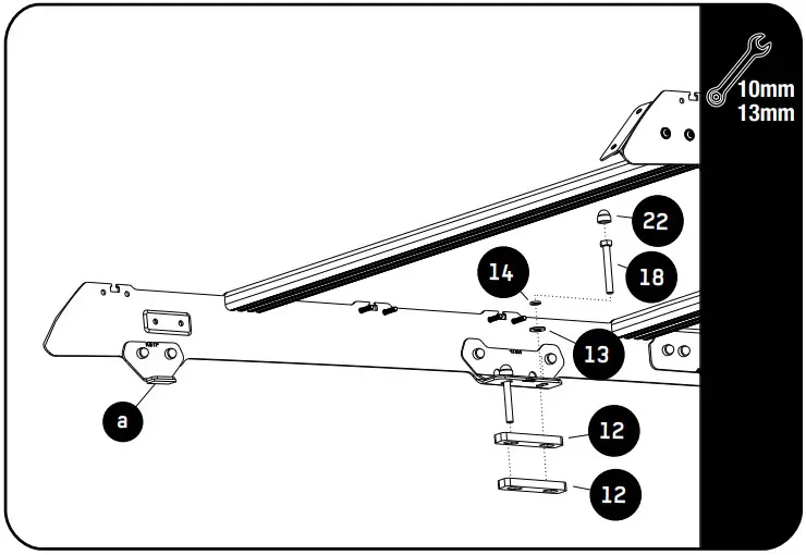
Place silicone into and around each of the fixing points. Place Spacers (Item 12) over the mounting holes.
Remove the backing from the double sided tape (4.2a) on the bottom of the Support Plate 01 (Item 3) and push the plate firmly down onto the body of the vehicle. Secure Rack assembly 2.2 using M6 x 12 x 1 Flat Washers, M6 Spring Washers and M6 x 30 Hex Bolts for front foot (Items 14, 15 & 17).
Place a bead of silicone down the length of each M6x20 bolt before inserting. Secure the middle and back feet using M8 x 19 x 2 Flat Washers, M8 Spring Washers and M8 x 60 Hex Bolts (Item 18, 13 & 14).
Fasten the front foot by inserting the fastener (item 17) through the double sided tape and securing into the Jack Nut fitted earlier. Fully tighten all fasteners. Place M6 and M8 Nut Caps over all hex Bolts.
PREPERATION
With the factory rails removed and starting at the front edge of the molding, measure and mark the dimensions as shown onto both the LH & RH ditch moldings.

Use denatured alchohol and ensure the ditch is clean from any residue where the Support Plate 01 (Item 3) will be resting on the ditch.
FIT AND SECURE
Place silicone into and around each of the fixing points. Place Spacers (Item 12) over the mounting holes.
Remove the backing from the double sided tape (4.2a) on the bottom of the Support Plate 01 (Item 3) and push the plate firmly down onto the body of the vehicle. Secure Rack assembly 2.2 using M6 x 12 x 1 Flat Washers, M6 Spring Washers and M6 x 30 Hex Bolts for front foot (Items 14, 15 & 17).
Place a bead of silicone down the length of each M6x20 bolt before inserting. Secure the middle and back feet using M8 x 19 x 2 Flat Washers, M8 Spring Washers and M8 x 60 Hex Bolts (Item 18, 13 & 14). Fully tighten all fasteners. Place M6 and M8 Nut Caps over all hex Bolts.
FIT AND SECURE
Refer to fitment guide RRAC234
LIGHT BAR WIND FAIRING ASSEMBLY
Refer to fitment guide RRAC195

COMPLETION8.1 Congratulations! You did it. Take a step back and admire your work!
INSTALL OTHER VEHICLE AND RACK ACCESSORIES
Now’s the time to visit your favorite Front Runner dealer in person or online.
IMPORTANT!
FRONT RUNNER RACK KITS OFTEN HAVE A HIGHER LOAD RATING THAN THE VEHICLES THEY ARE MOUNTED TO. PLEASE REFER TO YOUR SPECIFIC VEHICLE MANUFACTURER FOR A RECOMMENDED ROOF RATING. FRONT RUNNER CANNOT BE RESPONSIBLE FOR IMPROPERLOADING BEYOND THE VEHICLE MANUFACTURER’S STATED LOAD CAPACITY.
Be sure to tag us. We love to see our gear in action! #FrontRunnerOutfitters #BornToRoamShare your adventures on:![]()