Contents
Fronius 041 Smart Meter IP
Specifications
- Permitted ambient temperature: 100 – 240 V
- Nominal frequency: 208 – 480 V
- Voltage phase / neutral: max. 5 W
- Voltage phase/phase: 5 kA
- Self-consumption: IP20 / IP30 (Housing / Connections)
- Primary current: 3 TE (3 Modules DIN 43880)
- IP range: 5 kA
- Footprint: 3 TE (3 Modules DIN 43880)
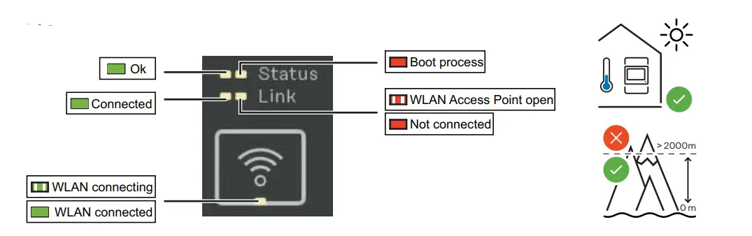
- LEDs: OK Connected, WLAN connecting, WLAN connected
Product Usage Instructions
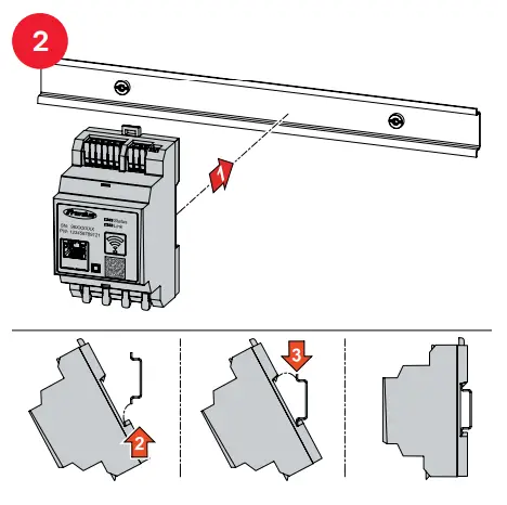
Mounting
- Mount the Fronius Smart Meter IP securely in a suitable location.
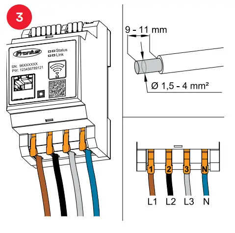
Power Wiring
- Connect the power supply within the specified voltage range.
Data Wiring
- Connect LAN or WLAN cables as required for communication.
Boot Process
- Ensure that the WLAN Access Point is open and not connected before proceeding.
Software-Version Update
- Follow the instructions provided to update the software version for full compatibility.
Outside Setup
- Use a mobile phone or PC to connect to the access point and follow the initial setup instructions.
The initial password for UI: 123
FAQ
- How do I update the software version of the Fronius Smart Meter IP?
- To update the software version, follow the steps outlined in the user manual provided with the product. Ensure proper connectivity and follow all instructions carefully.
- What is the default password for accessing the UI of the Smart Meter?
- The initial password for accessing the UI of the Smart Meter is , set to 123. You can change this password for security purposes after initial setup.
Fronius International GmbH declares that the radio equipment type Fronius Smart Meter IP is in compliance with Directive 2014/53/EU. The full text of the EU declaration of conformity is available at the following internet address: www.fronius.com
Technical Data
| Technical Data | |
| Permitted ambient temperature | from -25° to +55°C |
| Nominal frequency | 50- 60 Hz |
| Voltage phase / neutral | 100 – 240 V |
| Voltage phase / phase | 208 – 480 V |
| Self-consumption | max. 5 W |
| Primary current | 5 kA |
| IP range | IP20 / IP30 (Housing / Connections) |
| Footprint | 3 TE (3 Modules DIN 43880) |
Communication
| Communication | |
| WLAN / LAN | Modbus TCP |
| WLAN frequency band | 2,4 GHz |
| RS 485 | Modbus RTU |
| Terminating resistor for RS 485 | Configurable 0-1 |
| BIAS Network for RS 485 | Configurable 0-1 |
| Multimetering | Yes – up to 2 Smart meters (RTU) Modbus interface |
| Addressing (Modbus RTU) | In UI |
| Update possibility | Yes |
| CT V (Fronius CT V 100/250/400/600 A) | 1 – 5000 A / 333 mV |
LEDs
Software-Version:
- Fronius GEN24 & Tauro
- Full Compatibility (Version ≥ 1.24.1)
- Fronius Datamanager 2.0 (SnapInverter)
- Modbus RTU (Version ≥ 3.25.1)
- Full Compatibility (Version ≥ 3.28.1)
- Fronius Symo Hybrid
- Modbus RTU (Version ≥ 1.25.1)
- Full Compatibility (Version ≥ 1.28.1
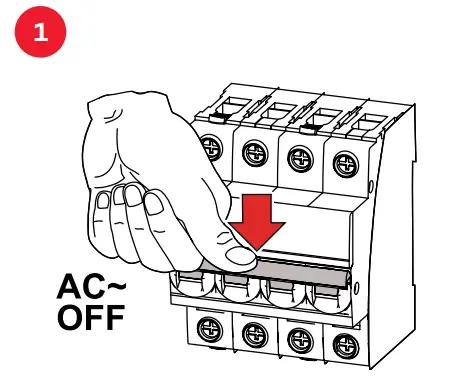
AC
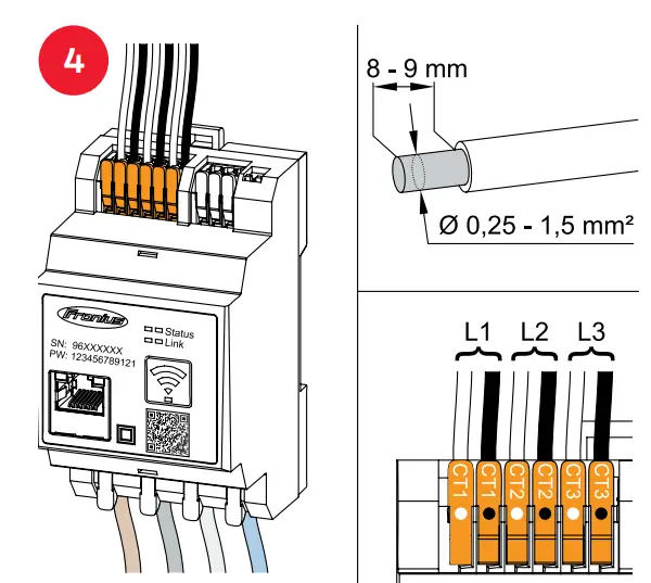
 Mounting
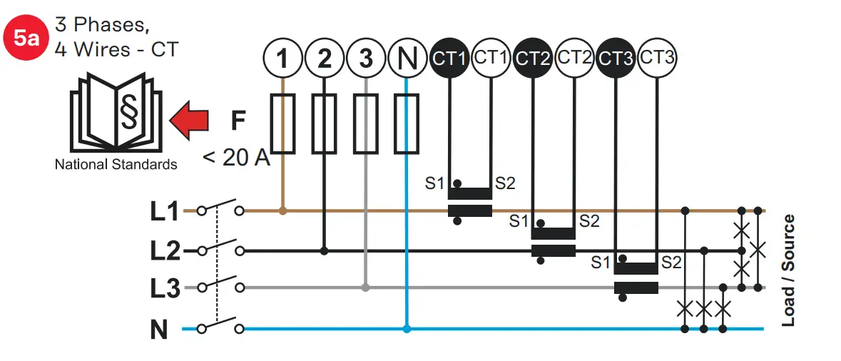
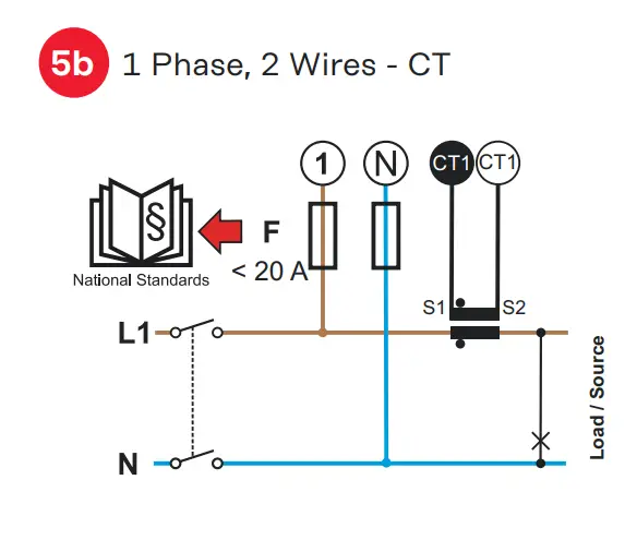
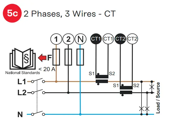
Power wiring
Data wiring
Technical Data (WLAN)
- Frequency band: channel 1-14 (2412-2472 MHz
- Radio-frequency power: <100 mW (<20 dBm)
- Max. antenna gain: 5.3 db
- Separation distance: 20 cm
- next step
Modbus RTU BIAS
Modbus RTU Terminating Resistor
AC
Setup
Detailed, country-specific warranty terms are available at: www.fronius.com/solar/warranty

manuals.fronius.com/html/4204260464