FMS BKS.D.7 Winder GLIDE Linear Actuator
Please contact your local representative.
Contents
Safety Information
All safety information, operating and installation regulations listed here ensure proper function of the device. Safe operation of the system requires compliance at all times. Noncompliance with the safety information or using the device outside of the specified performance data can endanger the personal safety.
Work with respect to operation, maintenance, retrofit, repair, or setting the device described here must only be performed by qualified personnel.
Presentation of Safety Information
- Danger that Could Result in Personal Injury
Danger, warning, caution
Type of danger and its source Possible consequences of nonobservance Measure for danger prevention - Note Regarding Proper Function
 Note
Note
Note regarding proper operation
Simplification of operation
Ensuring function
General Safety Information
![]() The linear actuators may not be subjected to loads outside of the specified values during installation and operation. In particular, the device must not be used outside of the temperature range and protection class.
The linear actuators may not be subjected to loads outside of the specified values during installation and operation. In particular, the device must not be used outside of the temperature range and protection class.
![]() The installation points on the machine frame must be designed correctly to properly accommodate the installation of the actuator.
The installation points on the machine frame must be designed correctly to properly accommodate the installation of the actuator.
![]() The linear actuator and related web guiding controller must be wired correctly.
The linear actuator and related web guiding controller must be wired correctly.
Product Information
Mode of Operation
The FMS winderGLIDE linear actuators feature a backlash-free ball screw driven by a BLDC motor. This enables precise corrections at high adjusting speeds. The linear actuator is connected to the web guiding controller using one cable only and an easily accessible connector. Its compact dimensions and various mounting options make the FMS winderGLIDE the ideal candidate for retrofit on existing systems.
Dimensions
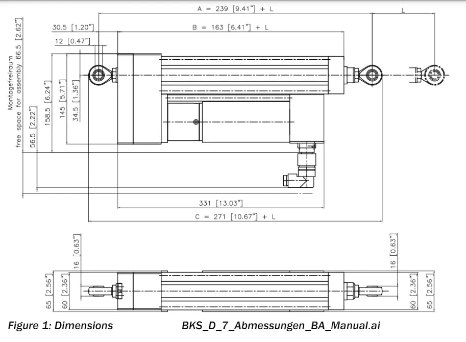
Table 1: Dimensions
| Dimensions mm (in.) | ||
| BKS.D.7.200 | BKS.D7.300 | |
| Stroke | 200 (7.87) | 300 (11.8) |
| A Centers of rod ends, fully retracted | 439 (9.4) | 539 (21.2) |
| B Total length main body | 363 (14.3) | 463 (18.2) |
| C Overall length, fully retracted | 471 (18.5) | 571 (22.5) |
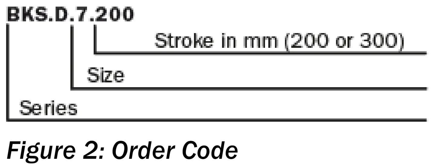
Order Code
Scope of Supply
The following is included in the scope of supply
- Linear actuator, rod ends on both sides
- Installation manual
The following is not included in the scope of supply
- Web guiding controller
- Mounting material
- Material sensor
- Connection cable to web guiding controller
Installation
Preparation
The FMS winderGLIDE linear actuators are defined as an “incomplete machine” in line with EC Directive 2006/42/EC, Article 2. When installing the FMS winderGLIDE, the following conditions must be met to ensure proper function and installation in a machine without negative impact on safety and health of persons:
 The linear actuators may not be subjected to loads outside of the specified values during installation and operation. In particular, the device must not be used outside of the temperature range and protection class.
- The installation points on the machine frame must be designed correctly to properly accommodate the installation of the actuator.
- The linear actuator and related web guiding controller must be wired correctly
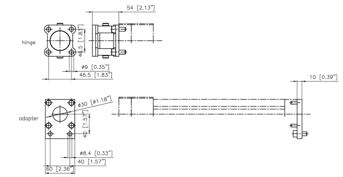
| Overview and combination of mounting accessories | ||
| Attachment to static end | Attachment to moving end | |
| Rod end (in scope of supply) | Yes | Yes |
| Clevis (accessories) | Yes | Yes |
| Hinge (accessories) | Yes | No |
| Flange | Yes | No |
Dimensions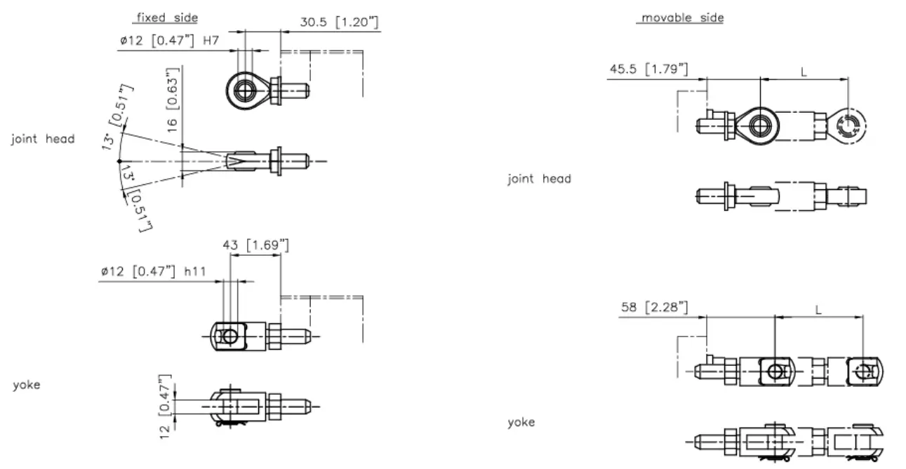
When tightening the rod end, you must secure the push rod against twisting using a hexagon wrench, otherwise the thread of the push rod may be damaged!!
The FMS winderGLIDE is designed for installation in horizontal position.
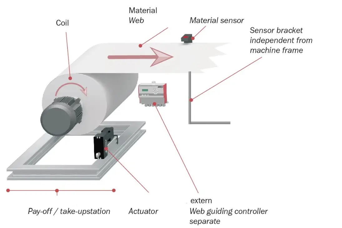
Figure 5: Installation on pay-off station
Tension_Control_Web_Guiding_Scheme_Schema.ai
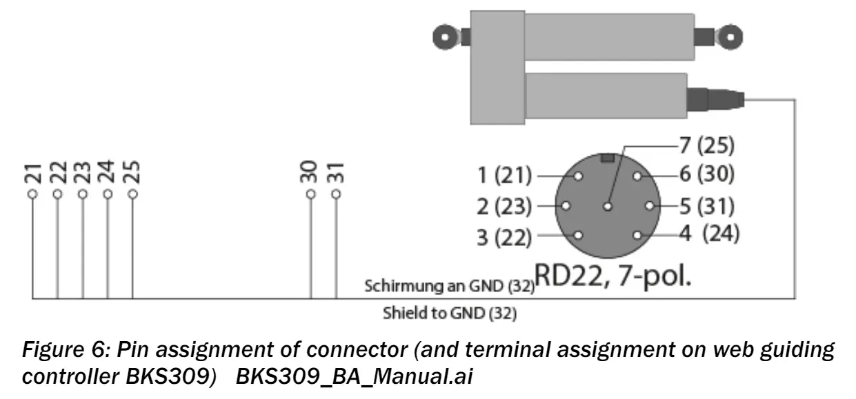
| Pin assignment of connector | |
| PIN | Assignment |
| 1 | 24V motor |
| 2 | GND |
| 3 | Velocity set point +/-10V |
| 4 | GND logic |
| 5 | 0 to 10V potentiometer |
| 6 | +10 V potentiometer |
| 7 | GND motor |
Technical Data
Table 4: Technical Data
| Technical Data | |
| Max. thrust force | 4’000N (900lbf) |
| Max. adjusting speed | 25 mm/s (0.98 in/s) |
| Drive | Stepper motor, 16 mm ball screw with 5 mm pitch |
| Temperature range | –10 to +50 °C |
| Protection rating | IP42 |
| Control accuracy | <±0.1 mm |
| Power consumption | Max. 160 W, from web guiding controller |
| Stroke limiting, travel measurement | Potentiometer |
CUSTOMER SUPPORT
Aspstrasse 6
8154 Oberglatt (Switzerland)
Tel. 0041 1 852 80 80
Fax 0041 1 850 60 06
[email protected]
www.fms-technology.com
2155 Stonington Avenue Suite 119
Hoffman Estates,, IL 60169 (USA)
Tel. +1 847 519 4400
Fax +1 847 519 4401
[email protected]
FMS (UK)
Aspstrasse 6
8154 Oberglatt (Switzerland)
Tel. +44 (0)1767 221 303
[email protected]