Contents
FFB-PLSVS, FFS-PLSVSP French Fitness FFB Black/Silver P/L Super V Squat Press

Product Information
- Product Name: FRENCH FITNESS FFB BLACK/ SILVER P/L SUPER V-SQUAT PRESS
- Model: FFB-PLSVS/ FFS-PLSVSP
- Assembly Manual
Features
- Color: Black/Silver
- Commercial Warranty: 10 Years Parts, 1 Year Labor
- 11 Gauge Steel
- 50 x 100 x 3mm steel tube
- Each frame receives an electrostatic powder coat finish to ensure maximum adhesion and durability
- Standard rubber feet protect base of the frame and prevent the machine from slipping
- Contoured cushions utilize a molded foam for superior comfort and durability
- Grips retained with aluminum collars, preventing them from slipping during use
- Hand grips are a durable urethane composite
- California Residents see Prop 65 WARNINGS
Tech Specs
- Chassis Assembly Left: 1 pc
- Chassis Assembly Right: 1 pc
- Chassis Connection Kit A: 2 pcs
- Chassis Connection Kit B: 1 pc
- Turntable Assembly: 1 pc
- Seat: 1 pc
- Spacer: 2 pcs
- Connecting Shaft 30*100mm: 1 pc
- Connecting Shaft: 1 pc
- Foot Pedal: 1 pc
- Gasket: 2 pcs
- Bell Shaft: 1 pc
- Hanger Guide: 4 pcs
- Rubber Cover: 2 pcs
- Pipe Plug: 8 pcs
- Large Non-slip Mat: 2 pcs
- Bearing Housing: 2 pcs
WARRANTY
10 Years Part, 1 Year Labor (Commercial)
Parts List(individual packaging)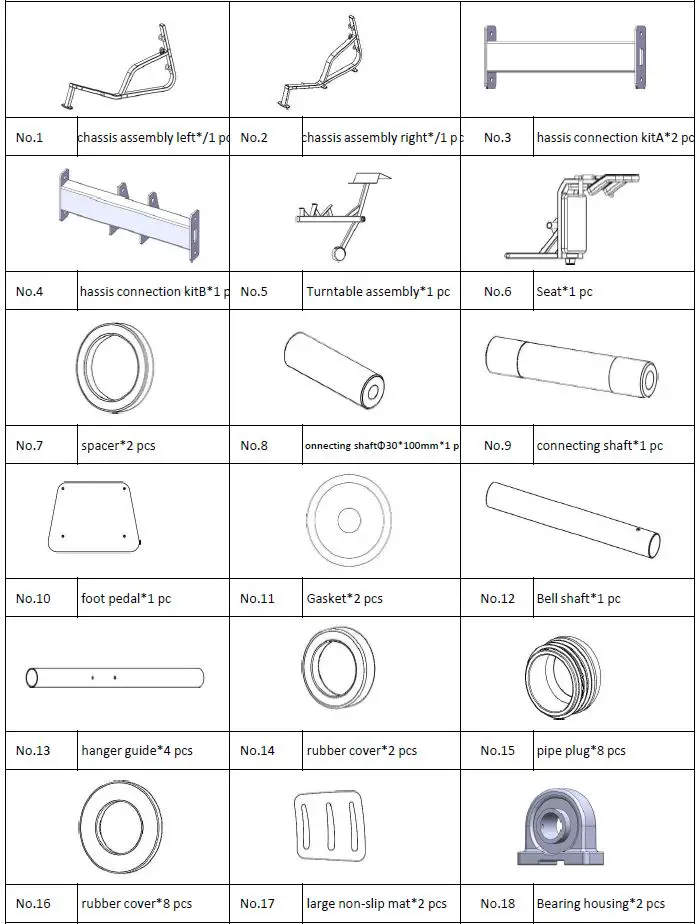
Blister Pack Screws List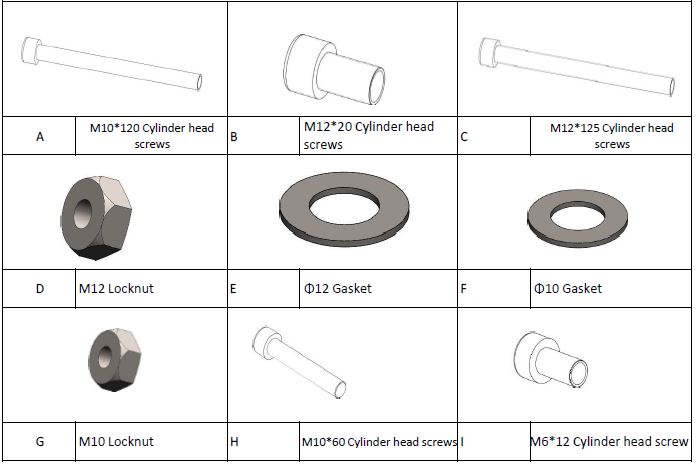
EXPLODED PART DIAGRAM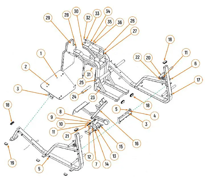
Product Usage Instructions
Assembly Steps
| Assembly steps | ||||||
| Step NO | Item NO | Name | Quantity | Item NO | Name | Quantity |
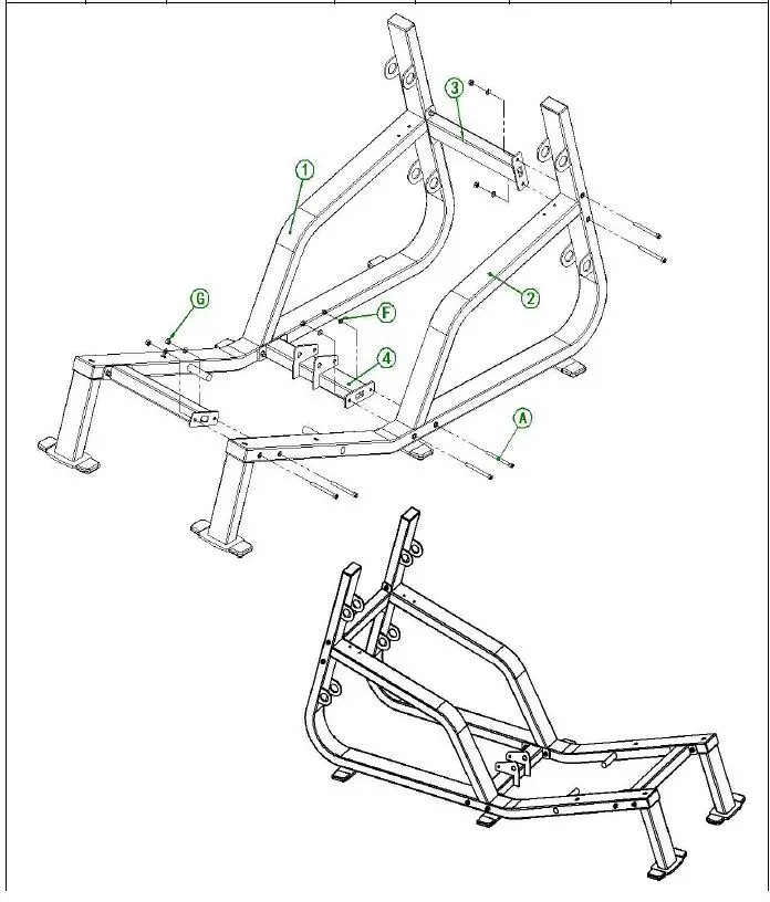
| 1 | No.1 | chassis assembly left | 1 | A | M10*120 Cylinder head screws | 6 |
| No.2 | chassis assembly right | 1 | F | Φ10 Gasket | 6 | |
| No.3 | Chassis connection kitA | 2 | G | M10 Locknut | 6 | |
| No.4 | Chassis connection kitB | 1 | ||||
 |
||||||
- Start by assembling the chassis. Attach the chassis assembly left and right using the chassis connection kits A and B.
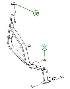
| No.1 chassis assembly left*1 pc | ||||||
| Step NO | Item NO | Name | Quantity | Item NO | Name | Quantity |
| No.19 | 50*100 Square tube plug | 2 | ||||
| No.20 | Rubber mat | 4 | ||||
 |
||||||
| No.2 chassis assembly right*1 pc | ||||||
| Step NO | Item NO | Name | Quantity | Item NO | Name | Quantity |
| No.19 | 50*100 Square tube plug | 2 | ||||
| No.20 | Rubber mat | 4 | ||||
 |
||||||
- Next, assemble the turntable assembly. Attach the connecting shafts, gaskets, and spacers as indicated in the assembly diagram.
| Assembly steps | ||||||
| Step NO | Item NO | Name | Quantity | Item NO | Name | Quantity |
|
2 |
No.5 | Turntable assembly | 1 | B | 12X20 Cylinder head screw | 2 |
| No.8 | connecting shaft 1 | 1 | C | 12*125 Cylinder head scre | 1 | |
| No.9 | connecting shaft 2 | 1 | E | Φ12 Gasket | 1 | |
| No.11 | Gasket | 2 | D | M12 Locknut | 1 | |
| No.7 | spacer | 2 | ||||
 |
||||||
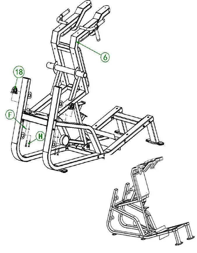
- Attach the seat assembly to the bearing housing using the provided screws and gaskets.
| Assembly steps | ||||||
| Step NO | Item NO | Name | Quantity | Item NO | Name | Quantity |
| No.6 | seat assembly | 1 | H | M10*60 Cylinder head screw | 4 | |
| No.18 | bearing | 2 | F | Φ10 Gasket | 4 | |
 |
||||||
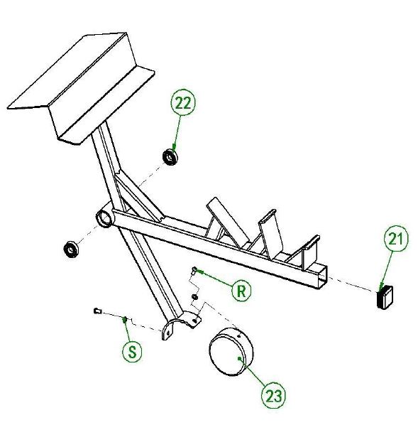
- Attach the hanger guides, rubber covers, and pipe plugs as indicated in the assembly diagram.
| No. Turntable assembly*1 pc | ||||||
| Step NO | Item NO | Name | Quantity | Item NO | Name | Quantity |
| No.21 | 50*50 Silencer | 1 | R | M8*16 Dome head screw | 2 | |
| No.22 | bearing 6004 | 2 | S | Φ8 Gasket | 2 | |
| No.23 | Counterweight | 1 | ||||
 |
||||||
- Finally, attach the large non-slip mats to the designated areas.
| No.6 seat assembly*1 pc | ||||||
| Step NO | Item NO | Name | Quantity | Item NO | Name | Quantity |
| No.24 | No.49 seat | 1 | T | M8*70 Cylinder head screw | 4 | |
| No.25 | Cushion | 1 | V | M8*25 Dome head screw | 6 | |
| No.26 | handle cover aluminum | 4 | S | Φ8 Gasket | 10 | |
| No.27 | rubber cannot tear up | 4 | W | 0 Countersunk Head Scr | 4 | |
| No.28 | No.81 plastic parts | 4 | ||||
| No.29 | shoulder pads | 2 | ||||
| No.30 | shoulder pads | 2 | ||||
 |
||||||
| Assembly steps | ||||||
| Step NO | Item NO | Name | Quantity | Item NO | Name | Quantity |
| No.13 | hanger guide | 4 | No.12 | Bell shaft | 1 | |
| No.14 | rubber cover | 2 | No.17 | large non-slip mat | 2 | |
| No.15 | Stainless steel pipe plug | 10 | No.10 | foot pedal | 1 | |
| No.16 | rubber cover | 8 | K | M10X25 Countersunk Head Screws | 4 | |
| J | M10*20 Cylinder head screw | s 2 | I | M6*12 Cylinder head screw | 8 | |
 |
||||||
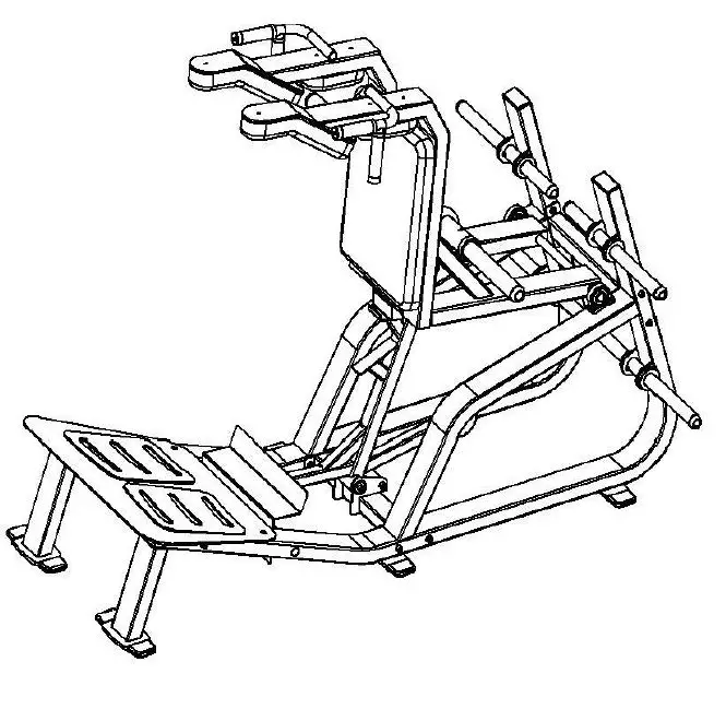
Note: Refer to the exploded part diagram for a visual representation of the assembly steps.