INSTALLATION & OPERATION MANUAL
Contents
EVO315-C
HOT WATER HEAT PUMP

evoheat.com.au 1300 859 933
Evo315-C Manual
1. Introduction
This manual contains information relating to the installation, troubleshooting, operation, and maintenance of this EvoHeat unit. Instructions in this manual must always be followed. Failure to comply with these recommendations will invalidate the warranty. Should you have any questions or require technical support, call the EvoHeat office on 1300 859 933 to speak to our team.
The data and information contained in this manual is correct at the time of publishing and is subject to change without notice. For the most up to date manual, contact EvoHeat directly.
|
TECHNICAL DATA |
Evo315-C |
|
| Storage Capacity |
L |
315 |
| Max Temperature Setting |
˚C |
60 |
| Power Input |
kW |
1.46 |
| Heating Output |
kW |
6 |
| Noise Rating |
dB(A) |
52 |
| Running Current |
A |
6.08 |
| Power Supply |
220-240V/1/50Hz |
|
| Water Inlet/Outlet Size |
mm |
20 (3/4”) |
| Auxiliary Heating |
kW |
4.8 |
| Operating Temperature Range |
˚C |
-5 to 43 |
| Hot Water Recovery |
L/hr |
126 |
| With Hydro Boost |
L/hr |
225 |
| Net Weight |
kg |
157 |
The EVO 315-C is the next evolution in water heating with advanced energy efficiency technologies and built-in smart features to ensure you’re provided with clean, safe,
and economical hot water all year round.
Conforms to AS 3498-2020 Australia and New Zealand
Measurement conditions: Instant heating: Ambient air temperature 20°C/15°C, water inlet 15°C, water outlet 55°C, highest setting temperature: 75°C
Working Temp Range
1. Ambient temperature is -5°C ~ 43°C (Heat Pump)
2. The max temperature of water tank is 70
Operating parameters: The range of the operating water pressures:
0.15~0.85MPa
2. Dimensions

- P&T valve
- Over heating protector
- Electric heater
- Drainpipe
- Condensation water outlet
- Hot water outlet
- Magnesium
- Cold water inlet
|
Evo315-C |
A | B | C | D | E | DIAMETER |
| 2250 | 1650.5 | 593 | 1411 | 1311 | 640 |

3. Quick Start Guide
QUICK START GUIDE
Evo315-C
DO NOT DRILL
Do not drill any fixings or attachments into the outer casing of the tank. Drilling into the outer casing of the tank may damage the heating coil and WILL VOID WARRANTY.
INITIAL STARTUP
- Press and hold for one second to power on the unit.
- To set the time:
a. Press once so the hour digit starts flashing,
b. Use to adjust the hour and press to confirm,
c. Repeat for the minute, day, month and year,
d. Press at any stage to cancel. - Press until is displayed. This will activate “Eco Heating” (Heat Pump only) mode and will provide the most efficient heating.
- During periods of unusually high hot water demand (such as additional occupants staying with you), you can activate “High Requirement” mode by pressing until is displayed.
- In any event where there is a failure within the system, the Electric Element (Hydroboost Mode) can be engaged with “one push activation” of the button until is displayed. This will provide emergency water heating until service can be attended.
- For adjustment of timers or activating vacation mode, please refer to our online tutorials at:
www.evoheat.com.au/tech-support
4. Safety Instructions
Ensure that all safety instructions and recommendations are always adhered to. Failure to comply with these recommendations could void the warranty and cause injury or death.
- Installation, repair, or relocations must only be done by a fully qualified technician.
- The Evo315-C must be installed to conform to all relevant Australian Standards and Industry Codes including but not limited to: Electrical & Electrical Safety, Plumbing & Hot Water Storage, Heat Pump Installation & Operation
- A circuit breaker must be installed for the unit.
- Ensure the unit has a good power connection and earthing to avoid the risk of electrical shocks.
- Ensure that there are no leaks on both the plumbing and drainage fittings.
- The unit must not be installed near flammable gas or have flammable aerosols sprayed in the vicinity.
- The base that the unit is installed on must be level and stable.
- If the supply cord is damaged, it must be replaced by a qualified service agent.
- This appliance must be installed in accordance with national wiring regulations.
- Installation must also comply with any local, state or federal codes at the installation site. Failure to comply can void your warranty, damage your unit or possible cause injury or death. Plumbing must comply with AS/NZS3500.4
- Before obtaining access to terminals all supply circuits must be disconnected.
- A P&T valve MUST be installed in the tank. When the tank pressure reaches 0.85MPa or when the tank temperature reaches 99°C, the P&T valve will open automatically so as to reduce the pressure or temperature decrease.
- In the event of the unit malfunctioning, shut off the power supply and contact your supplier or EvoHeat.
- In order to use the unit correctly, run the unit at environment temperature -5°C – 43°C
- The unit contains sophisticated electronic devices, do not use unsafe water sources such as lake or groundwater.
- The unit produces hot water and will also have hot fittings, therefore should not be touched to avoid injury.
- Do not drill any fixings or attachments into the outer casing of the tank. Drilling into the outer casing of the tank may damage the heating coil and WILL VOID WARRANTY.
- If the unit stops and you restart the unit or turn it on manually, the unit will not start to run again for approximately 3 minutes. This is a protection feature to safeguard the compressor.
- The handle of the P&T safety valve should be tested once every six months to remove the calcium carbonate deposits and guarantee there is no blockage in the device.
- Once installation is complete, check that all connections are secure before the power is turned on.
- The installer is to explain to the end user how to operate and maintain the unit in accordance with this instruction manual.
- Evo Industries Australia Pty Ltd will not be held responsible for any damages or injuries caused by the incorrect installation of this hot water system.
- A maintenance programme must be carried out as recommended in this manual to ensure ongoing reliability.
To reduce the risk of excessive pressures and temperatures in this water heater, install temperature and pressure protective equipment required by local codes and no less than a combination temperature and pressure relief valve certified by a nationally recognized testing laboratory that maintains periodic inspection of production of listed equipment or materials, as meeting the requirements for Relief Valves and Automatic Gas Shutoff Devices for Hot Water Supply Systems, ANSIZ21.22. This valve must be marked with a maximum set pressure not to exceed the marked maximum working pressure of the water heater. Install the valve into an opening provided and marked for this purpose in the water heater, and orient it or provide tubing so that any discharge from the valve exits only within 6 inches above, or at any distance below, the structural floor, and does not contact any live electrical part. The discharge opening must not be blocked or reduced in size under any circumstances.
Hydrogen gas is produced in a hot water system served by this heater that has not been used for a long period of time (2 weeks or more). Hydrogen gas is extremely flammable. To reduce the risk of injury under these conditions, it is recommended that the hot water faucet be opened for several minutes at the kitchen sink before using any electrical appliance.
The appliance is fitted with means for disconnection from the supply mains having a contact separation in all poles that provide full disconnection under overvoltage category III conditions, and these means must be incorporated in the fixed wiring in accordance with the wiring rules.
|
WARNING |
| THIS PRODUCT CONTAINS A BUTTON BATTERY
If swallowed, a lithium button battery can cause severe or fatal injuries within 2 hours. Keep batteries out of reach of children. If you think batteries may have been swallowed or placed inside any part of the body, seek immediate medical attention. |
5. Installation
5.1 System Installation
Upon receiving the unit, check the packaging for any obvious signs of damage. Inform EvoHeat immediately if there is any evidence of rough handling.
Do not drill any fixings or attachments into the outer casing of the tank. Drilling into the outer casing of the tank may damage the heating coil and WILL VOID WARRANTY.
Drain the water tank through the drain valve at the bottom part of the unit.
The P&T valve attached with the unit must be installed. Failure to do so will cause damage to the unit and possible personal injury.
Do not use stainless steel fittings to connect directly with other metals to prevent galvanic corrosion.
Note: A pressure releasing valve is to be fitted within the installation. Spec of P&T valve: Pressure: 0.85MP Temperature: 99°C
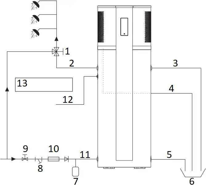
- Tempering Valve
- Water Outlet
- P&T Valve
- Condensate Outlet
- Drainpipe
- Barrel-drain
- Thermal expansion tank
(if required) - Y-shaped Filter
- Tap Water
- Pressure reducing valve
- Water Inlet
- Magnesium
- Notice:
Tempering valve required
Water Inlet or Outlet Pipes: The specification of the water inlet and outlet thread is BSP3/4 (internal thread). Pipes must be heat-resistant and durable.
Piping for the P&T Valve: The spec of the valve connecting thread is BSP3/4 (internal thread). After installation, confirm that the drainpipe outlet is exposed in the air. When the flexible drainpipe is joined to the pressure relief orifice of this valve, ensure that the flexible drainpipe is pointing downwards and exposed in the air.
5.2 Handing & Transportation
The unit should be stored and/or transported in its shipping container in an upright position and without water charge. For transport over short distances, and provided due care is exercised, an inclination angle of up to 30 degrees is permitted. During transport and storage, ambient temperatures of -10 to +60 degrees Celsius are permissible.
|
Forklift Transportation The unit must remain mounted on the pallet and lifted at minimal speed. Due to its top heaviness, the unit must be secured against tipping over and placed on a level surface. |
Manual Transportation
Ensure that the maximum permissible inclination angle of 60 degrees is not exceeded. If transport in an inclined position cannot be avoided, the unit should be left to rest at least one hour after it has been moved into final position before operation. |
5.3 Location of Installation
The Evo315-C is designed for external installation, however, where possible installing the unit under the house eaves or in a sheltered environment may help prolong the life of the system.
Heat pumps operate most efficiently with warmer air temperatures, and the outlet air from the unit will always be colder than the inlet air. Therefore, it is advisable to install the unit so it receives the warmest air temperatures possible and that the cold air is not able to recirculate back into the unit.
5.3.1 Indoor Installation
- The unit may be able to be installed in an unventilated room exceeding 25m³ in volume.
- Venting of cold air is advised to prevent the air temperature dropping and lowering the efficiency of the unit.
- Think of the unit as a 3kW air conditioner for the effect it will have on a closed room.
| TO COOL A ROOM
Install the unit so the outlet from the heat pump is blowing INTO the room. The room MUST have some form of air outlet otherwise the performance of the unit will suffer significantly. |
TO MAINTAIN NORMAL ROOM TEMPERATURE
Install the unit so the outlet from the heat pump is blowing OUTSIDE the room. The room MUST have some form of air inlet otherwise the performance of the unit will suffer significantly. |
5.4 Airflow Clearances
The Evo315-C must be installed with sufficient clearances to allow airflow to circulate through the unit, it is advised to keep a minimum gap between walls/fences etc of:
- 1000mm on the air inlet & outlet sides
- 300mm rear clearance
- 600mm overhead clearance
Without sufficient airflow, discharged cold air will recirculate into the unit and consequently lower the heating efficiency.
If the installation location does not comply with these suggested clearances, contact EvoHeat’s Tech Support to discuss possible solutions.
5.5 Cable Connection
The power cable for power supply of the unit is stored in the back of the unit. The unit requires an isolating switch as required by local laws. If the power cord is damaged, it must be replaced by a qualified electrician.
5.6 Filling the Tank
Open a hot water tap inside the house. Open the cold-water inlet valve into the Evo315-C to fill the tank. When water begins flowing out of the hot water tap inside the premises, turn off the hot water tap.
5.7 Initial Start-Up
|
PRE-INSPECTION Check the water supply to the tank and pipe connections for possible leaks. Check that the following devices are installed and operating correctly:
Check that all power connections are secure before switching on. Check that the installation space is adequate. |
TRIAL OPERATION Switch on the unit by using the controller. If any unusual noises occur, switch the power off and consult your provider. The parameters have been pre-set to a temperature of 60 degrees. Check that the unit is operating by looking for an increase in water temperature over time. |
6. Operation
6.1 The Controller
|
ON/OFF |
Turn the unit on or off. | |
|
UP |
Select options to increase values | |
|
DOWN |
Select options to decrease values | |
|
CLOCK |
Set the clock or the timer. | |
|
HYDROBOOST |
Turn on/off the electric heater | |
|
MODE |
Switch unit running modes or save setting parameters | |
|
TOUCH TIMING |
Touch timing settings | |
|
HEATING MODE |
The unit will start according to the water temperature and target temperature. The electric heater will not start immediately. After 200 minutes, the unit will judge if it has reached target temperature. If not, the electric heater will start. | |
|
ECO HEATING MODE |
The heat pump system will start according to the water temperature and target temperature. The electric heater always will be off. | |
|
INTELLIGENT MODE |
The unit will automatically judge the operation mode according to the ambient temperature. | |
|
HIGH REQUIREMENT MODE |
The difference between heating mode and high requirement mode is the delay time of electric heater. In the high demand mode, the electric heater will start without delay, which can help the user to heat water quickly in a short time. | |
|
VACATION MODE |
Enable Vacation mode | |
|
FAN |
Fan is on | |
|
HYDROBOOST |
The Hydroboost setting is on | |
|
DEFROST |
The unit is defrosting | |
|
LOCK |
Keyboard is locked | |
| SET |
PARAMETER SETTING |
Parameter is adjustable |
|
SET TEMP REACHED |
Set temperature has been reached and the unit will shut off automatically | |
| DOWN |
LOWER TANK TEMP |
Temperature of the lower tank |
| min |
MINUTE |
Minute value is being set |
| S |
SECOND |
Second value is being set |
|
WI-FI |
State of Wi-Fi connection *Only available as an optional upgrade |
6.2 Operating Functions
EvoHeat have developed a YouTube Channel with video walkthroughs of the different controller functions.
Scan the QR code or head to our channel to view the videos we have available https://www.youtube.com/@evoheatpumps

6.2.1 Startup & Shutdown
Press and hold for 0.5 seconds in the standby screen of the controller to turn the unit on. The main display will now show the water outlet temperature.
Press and hold for 0.5 seconds in the running screen of the controller to turn the unit off. The main display will now show “OFF”.
The unit will dim the screen and display the standby screen when the controller has not been touched for a minute. Touch the power button to wake it.
Note: The ON/OFF button can only be used to turn the unit on/off in standby or on the running screen of the controller.
OFF STATE ON STATE
- Hold for half a second.
- Outlet water temperature
- Current time
6.2.2 Switching Modes
From the running screen, press to select one of the modes: Heating, Eco Heating, Intelligent, High requirement, Vacation.
Heating Mode Eco Heating Mode Intelligent Mode
High Requirement Mode Vacation Mode
Press to alternate between different modes.
6.2.3 Locking the Controller
To both lock and unlock the controller, press and hold the button for 5 seconds.
When the controller is locked, a lock symbol will appear on the bottom right.
6.2.4 Setting & Checking the Target Temperature
In the standby or running interface, press or once to check the target temperature of the outlet water.
Press or again to change the target temperature.
After making changes to the desired temperature, press to confirm or to cancel, then return to the previous screen.
If the keypad is left idle for 5 seconds, the controller will exit the menu automatically and apply any changes that were made.
Example: The target temperature is 40°C, the actual outlet water temperature is 18°C.
- Outlet water temperature
- Press or to check the target temperature
- Press the arrow key again to adjust the target temperature
- Target temperature
- Save changes by pressing
- Cancel changes by pressing
6.2.5 Hydroboost Setting
Also known as the Electric heater, the Hydroboost setting allows higher levels of hot water to be produced. When there are high hot water usage requirements (such as guests staying), this function may come in useful.
The Hydroboost setting can be turned on when the unit is heating or in standby mode.
Press once to turn on Hydroboost and press again to shut it off. When activated, will light up on the main display.
Running State Off State
- Hydroboost Mode
6.2.6 Force Defrost
In the extremely unlikely circumstance of the unit icing up (for example, if the unit was installed inside with no ventilation), this function can be applied.
When the unit is off, press and hold for 10 seconds to enable the forced defrosting function. The defrosting symbol will light up. Press for 10 seconds again to exit the forced defrosting function.
6.2.7 Sanitech System
The Sanitech feature’s purpose is to keep the water free of bacteria such as Legionella by heating the tank water to 70°C for one 30-minute period every week at midnight.
An instance when you may want to alter the Sanitech function is if you have solar and would prefer the Sanitech to run during the day, for example at 12pm, rather than midnight. You would need to change the g03 parameter to 12 (12pm).
Press and hold for 10 seconds a single time to access the parameter menus. When the screen displays ‘000’ press the up/down arrow keys until the number ‘066’ is displayed, then press the key. Use the up/down arrow keys to navigate to the correct parameter value as shown in the below table and press the key to open that value.
Change the value using the up/down arrow keys and press the key to save changes. Press to exit the menu.
|
Description |
Parameter | Default | Range |
| Sanitech Target Temperature | g01 | 70 degrees |
30-70 degrees |
|
Sanitech Temperature Hold Time |
g02 | 30 minutes | 0-90 minutes |
| Sanitech Start Time (24-hour clock) | g03 | 0 hours |
0-23 hours |
|
Sanitech Operation Cycle |
g04 | 7 days |
7-99 days |
Changing these settings may lower or disable the unit’s ability to ensure your water is free from bacteria.
To disable the Sanitech feature, simply adjust the Sanitech target temperature (g01) to a figure below the normal water storage temperature (generally 50 degrees or lower).
6.2.8 System Date & Time
In the standby or running interface, press once, the hour digit will flash indicating it is being altered.
Press the or to change the hour setting, then press to confirm. Repeat this to change the minute value.
- Press , then press or to change the hour
- Then press to confirm
- press or to change the minute
- Then press to confirm
- Press , then press or to change the month
- Then press to confirm
- press or to change the day
- Then press to confirm and save changes.
6.2.9 Setting & Cancelling Timers
Timers can be set in standard mode, economic mode, auto mode & fast heating mode. They can be set by using buttons or using the touch timing circle. The unit will run during the lit time periods and stop in the dim areas.
|
Touch Method
|
Button Method
|
Example: Setting the unit to run from 7-11am & 4pm-6pm using Touch mode.
- Flashing
- Press and hold for 2 seconds
- Press Cell 8, it will begin to flash
- Press Cell 18, it will light grid 8-18.
- Press Cell 12, it will begin to flash
- Press Cell 16, 12-16 will become dim
(timer is off during this period) - Press to save timer settings.
- The small cell at 0 will stop flashing when completed.
To cancel a timer once it has been set, hold down the CLOCK button for 2 seconds until the timer display begins flashing (as you would set the timer).
Press the POWER button while the timer is flashing to cancel it. The yellow timing periods will disappear when the timer has been cancelled.
6.2.10 Vacation Mode
Vacation Mode allows you to turn the unit off to conserve power for an extended period of time, and restart operation on a date you specify. This ensures you have hot water waiting for you upon your return.
Ensure the unit is ‘OFF‘ before setting vacation mode. The date you set in this mode will determine what date the unit starts back up.
After selecting vacation mode, press and hold for 2 seconds, the ‘month’ value will begin to flash in the display area. Press the UP or DOWN arrows to display the desired month, then press to confirm and move to altering the ‘day’ value.
The ‘day’ value will flash when it is selected, use the arrow keys to select your desired start day, then press to save all changes and exit back to the main interface.
Note: Format is mm/dd
Example: The unit will start up on September the 28th.
- Month value flashing
- Press and hold for 2 seconds
- Use or to change month
- Press to save and alter day
- Use or to change day
- Press to save all changes
6.2.11 Fan/Ventilation Function
This function may come in useful if the system is installed inside and the fan settings need to be adjusted to suit ducting or external ventilation.
The fan speed (High Speed, Low Speed or Off) can be controlled by the fan mode on the controller.
| Fan mode symbols: High Speed Low speed No Fan Icon: offNote: When H02 is set to 0, there is no ventilation function. Note: when the compressor is on, the fan will always run at high speed. |
|
When the parameter HO2 is set to 1, press the for 2s.
Once you hear a beep you can set the ventilation mode. Press for 2s, this will change the fan speed.
Continue to press for 2s until you reach your preferred speed.
7. Troubleshooting
7.1 Parameters Explained
| No. | Meaning | Range | Default value | Details |
| Hardware parameters | ||||
| /01 | The usage of the O05 port | 0/2 | 0 | 0-Low speed / 2-Solar water pump |
| /02 | High temperature disinfection target temperature | 0/2/3 | 0 | 0-No output / 2-Solar water pump / 3- Solar drain valve |
| Defrost parameters | ||||
| D01 | Heating enter defrosting coil temp value | -30~0 | -3 | |
| D02 | Heating exit defrosting coil temp value | 0~30 | 13 | |
| D03 | Heating defrost cycle | 30~90min | 45min | |
| D04 | Heating the maximum defrosting time | 1~20min | 8min | |
| D05 | Heating the minimum defrosting time | 0~D04 | 3min | |
| D06 | Heating the minimum defrosting time | 0~2 | 0 | 0-Standard / 1-Economic / 2-Intelligent |
| D07 | Intelligent defrost temperature conversion point | -10~20 | 4 | |
| High temperature disinfection parameters | ||||
| G01 | High temperature disinfection target temp | 30~70 | 70 | |
| G02 | High temperature disinfection running time | 0~90min | 30min | When G02= 0, no high temperature disinfection function |
| G03 | High temperature disinfection startup time | 0~23H | 0h | |
| G04 | High temperature disinfection cycle | 7~99Days | 7 | |
| EEV parameters | ||||
| E01 | EEV adjustment mode | 0/1 | 1 | 0- Manual / 1- Auto |
| E02 | EEV target overheat temp | – 20~20 | 5 | |
| E03 | EEV initial steps | 0~500 | 240 | |
| E04 | EEV minimum steps | 0~500 | 100 | |
| E05 | Defrosting EEV steps | 0~500 | 480 | |
| System parameters | ||||
| H01 | Whether enable the power down memory function | 0/1 | 1 | 0-No / 1-Yes |
| H03 | Heat source mode | 0 | 0 | |
| H07 | Fahrenheit / Celsius | 0/1 | 0 | 0-Celsius / 1-Fahrenheit |
| H30 | Unit address | 4(1~255) | 1 | |
| H31 | Remote control mode | 0/1 | 1 | 0-Centralized control / 1-
DTU&WIFI |
| H32 | Status parameter feedback to cloud cycle | 1~255min | 5 | |
| H98 | Type of unit parameter | 2/3 | 2 | 2-0*08 / 3-0*18 |
| H99 | Main display temp showing adjustment | 0/1 | 1 | 0-No / 1-Yes |
| Solar water pump parameters | ||||
| N01 | Which temp sensor used for controlling the solar water pump | 0/1 | 0 | 0-Water tank bottom temp sensor 1-Water tank top
temp sensor |
| N02 | The maximum running time of the solar water pump | 1~30min | 15min | |
| N03 | The solar water pump startup return difference | 0~20 | 5 | |
| N04 | Whether enable the night cooling mode | 0/1 | 0 | 0-No / 1-Yes |
| N05 | Cooling function startup time | 0~23h | 0h | |
| N06 | Cooling function shutdown time | 0~23h | 6h | |
| N07 | Night cooling startup temp | 40~90 | 70 | |
| N08 | Night cooling shutdown temp | 1~40 | 10 | |
| N09 | Solar drain valve temp setting value | 50~90 | 68 | |
| N10 | Solar water pump shutdown temp setting value | 50~90 | ||
| N11 | Whether enable the independent solar control function | 0 / 1 | 0 | 0-Disable / 1-Enable |
| Temperature parameters | ||||
| R01 | Hot water target temp setting value | 38~75 | 55 | |
| R03 | Heating, the lower temp return difference setting value | 1~20 | 5 | |
| R04 | Whether enable the electric heater independent setting value | 0 / 1 | 0 | 0-Disable / 1-Enable |
| R05 | Electric heating temp setting value | 30~90 | 55 | |
| R06 | Electric heat startup delay | 0~450min | 200min | |
| R07 | Whether the electric heater replace the compressor | 0 / 1 | 1 | 0-No / 1-Yes |
| R08 | Electric heater replace the compressor ambient temp | -20~10 | -5 | |
| R09 | Electric heater zero delay startup ambient temp | 0~30 | 5 | |
| R10 | Electric heater delay startup ambient temp | 10~40 | 25 | |
| R12 | The compressor force to shutdown temp | -30~-5 | -15 | |
| R14 | Replacement value of external heat source target temperature | 10~60 | 45 | |
| R15 | The compressor limit temp under high ambient temp | 55~80 | 78 | |
| R17 | Whether enable the top temp sensor for controlling the compressor startup | 0 / 1 | 0 | 0-Disable / 1-Enable |
| R18 | Heating, the top temp return difference setting value | 1~20 | 1 | |
| R19 | The compressor shutdown ambient temp 1 | 30~90 | 65 | |
| R20 | The compressor shutdown ambient temp 2 | 30~90 | 60 | |
| Timing parameters | ||||
| L01 | Whether enable the vacation mode | 0 / 1 | 0 | 0-Disable / 1-Enable |
| L02 | The vacation mode: Year | 0~99Y | 0 | |
| L03 | The vacation mode: Month | 0~12M | 0 | |
| L04 | The vacation mode: Day | 0~31D | 0 | |
| L05 | Whether enable the timing on/off function | 0 / 1 | 0 | 0-Disable / 1-Enable |
| L06 | Timing on period 1: Hour | 0~23h | 0 | |
| L07 | Timing on period 1: Minute | 0~59min | 0 | |
| L08 | Timing off period 1: Hour | 0~23h | 0 | |
| L09 | Timing off period 1: Minute | 0~59min | 0 | |
| L10 | Timing on period 2: Hour | 0~23h | 0 | |
| L11 | Timing on period 2: Minute | 0~59min | 0 | |
| L12 | Timing off period 2: Hour | 0~23h | 0 | |
| L13 | Timing off period 2: Minute | 0~59min | 0 | |
| Switch status parameters | ||||
| S01 | Remote on/off switch | CL / OP | Close | |
| S03 | Low pressure protection switch | CL / OP | Close | |
| S04 | High pressure protection switch | CL / OP | Close | |
| S05 | Time-lapse signal switch | CL / OP | Open | |
| S06 | External setting switch | CL / OP | Open | |
| Temperature status parameters | ||||
| T01 | Ambient temp | -30~93 | / | |
| T02 | Water tank bottom temp | -30~93 | / | |
| T03 | Water tank top temp | -30~93 | / | |
| T04 | Coil temp | -30~93 | / | |
| T05 | Suction temp | -30~93 | / | |
| T06 | Solar control temp | -30~93 | / | |
| T10 | App/wire controller display temp | -30~93 | / | |
| T20 | Enter parameter over-range protection times | 0~65535 | / | |
| T21 | Memory chip EEPROM storage times | 0~30000 | / | |
7.2 Error Codes
|
Malfunction |
Display | Cause |
Solution |
| Bottom water temp. sensor failure |
P01 |
|
|
| Top tank water temp. sensor failure |
P02 |
||
| Ambient temp. sensor failure |
P04 |
||
| Coil temp. sensor failure |
P05 |
||
| Suction temp. sensor failure |
P07 |
||
| Solar control temp. sensor failure |
P034 |
||
| High pressure protection |
E01 |
|
|
| Low pressure protection |
E02 |
|
|
| Communication failure |
E08 |
|
|
| Anti-freeze protection in winter |
E09 |
|
|
8. Appendix
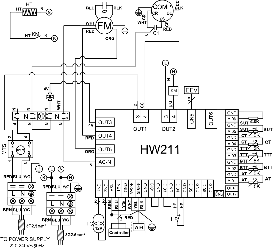
8.1 Wiring Diagram
AT: Ambient temperature
BTT: Bottom of tank temperature
COMP: Compressor
CT: Coil temperature
4V: 4 way valve
EEV: Electronic expand valve
FM: Fan motor
HP: High pressure protection
HT: Heater
KM: AC contactor
MTS: Mechanism temperature switch
SUT: Suction temperature
TC: Transformer
TTT: Top of tank temperature
8.2 Wi-Fi Module Connection (Optional)
Note: If you do not have a Wi-Fi module to install, simply push the cord entirely behind the front panel.
The optional Wi-fi Control upgrade can be purchased to allow you to remotely control your EvoHeat hot water heat pump from your phone.
Newly installed units will have a small cable that protruding out from behind the front panel with a small waterproof cover.
If you are installing the Wi-Fi module, simply connect the cable of the Wi-Fi module to the one that protrudes.
Once the Wi-Fi module has been connected, ensure that the connection part of the cable is placed behind the front cover.
The module must be placed with the cord coming downwards to protect it from water.

8.3 Exploded Parts View

| No. | Material Code | Material name | Specification |
| 1 | 40000-240061 | Bottom foam | Foam Φ542 white |
| 2 | 38000-220079 | Nozzle Decorative Cover | Positioning of 38 High 28 PE Tube Head |
| 3 | 20000-220165 | 02 Electric Heating Covers | Round 130*37 Flame Retardant ABS+PC Grey (RAL7001) |
| 4 | 80500016 | Electric heating tube | 4.8kW 240V G1 “Stainless Steel External Thread |
| 5 | 38000-220079 | Nozzle Decorative Cover | Positioning of 38 High 28 PE Tube Head |
| 6 | 40000-220060 | 05 Electric Heating Covers | Runway-shaped 200 x 140 x 35.5 Flame Retardant PC 940A-116 Grey (RAL7001) |
| 7 | 20000-130193 | P&T valve | PTR20 R3/4″*Rp3/4″internal and external threaded brass |
| 8 | 83400054 | Foam guide ring | 450 * 450 * 183 smooth black EPP foam |
| 9 | 80704838 | Fan Fixed Plate | Galvanized sheet 1.0 Black finish 9005 |
| 10 | 38000-270001 | Motor blade | 364*115 Axial Flow Fan Motor |
| 11 | 20000-330443 | Alternating current dynamo | YDK40-6N |
| 12 | 80702659 | Motor bracket | Galvanized sheet 1.2 Black finish 9005 |
| 13 | 80900421 | KP cover | 640*22 ABS Black Gloss 9005 Plastic Absorption |
| 14 | 80708081 | KP Top Cover | Galvanized sheet 0.8 gray-white matte 9006 |
| 15 | 80704839 | Fan top cover | Galvanized sheet 1.0 Black finish 9005 |
| 16 | 80704842 | Front Aluminium Alloy Plate | Aluminium alloy plate 1.8 length 1860 width 200 |
| 17 | 80600553 | Finned heat exchanger | 473 x 546 x 7 x 5 piece spacing 1.6 |
| 18 | 80100110 | Compressor and its accessories | WHP06000BSX-C8DU |
| 19 | 20000-140456 | Electronic expansion valve | DPF(TS1)1.65C-07 |
| 20 | 38004-220020 | 640 water pan | Φ640ABS Black (RAL9011) Injection Molding |
| 21 | 20000-360051 | Mechanical Temperature Controller for Water Tank | KSD301C C-207R 85 C 45A (RoHS) |
| 22 | 72200315 | Wire controller | |
| 23 | 80708083 | Electrical Box Covers | DX51D+Z80 t0.8 black 9005 |
| 24 | 70201187 | Electrical Box | |
| 25 | 20000-260028 | Water tank foot | Horseshoe-shaped 140 x 63 x 16.5 black rubber belt groove |
| 26 | 2000-1445 | Filter | Φ9.7-Φ6.5( Φ19) T2Y2 |
| 27 | 40000-210372 | 640 floor | Galvanized sheet 650 x 650 x 1.2 (shear angle) |
| 28 | 20000-210293 | Front panel connection plate | Galvanized sheet 1.0 sliver gray finish 9007 |
| 29 | 80600882 | Tank liner 315L | Φ542 enamel water tank G1 screw heating 4.8kw Thickness 2.5 End Cover Thickness 3.0 |
| 30 | 80708079 | Galvanized Shell | Φ640 x 1633 x 0.5 gray-white matte 9006 |
8.4 Use of the P&T Valve
The P&T valve is used to prevent the temperature or pressure becoming too high inside the tank. When the temperature or pressure reaches the set value, the valve will open automatically to force the pressure or temperature to decrease
The handle of the safety valve should be tested once every six months to remove the calcium carbonate deposits and guarantee there is no blockage in the device. Take care to avoid burns as the temperature of the discharging water is very high.
Vent pipes should be thermally insulated to prevent safety risks caused by freezing pipes in winter.
P&T valve: Model: PTR-20, action temperature: 99°C, action pressure:0.85MPa
WARNING: Failing to operate the relief valve easing gear at least once every six months may result in the water heater exploding. Continuous leakage of water from the valve may indicate a problem with the water heater.
8.5 Using the Overheating Protector
The overheating protector is used to turn the power off in an emergency or with power supply issues, preventing the water from being heated too high.
A thermal cut-out could indicate a possibly dangerous situation. Do not reset the thermal cutout until the unit has been serviced by a qualified technician. Contact EvoHeat for a service if this occurs before attempting to reset.
To return the unit to its normal operation status by resetting manually:
a) To access the overheat protector, remove the front dark grey controller panel.
b) Remove the 3 screws on the front panel and push the front cover upwards.
c) Remove the remaining screws which cover the overheat protector panel.

Remove the screws and open the cover

Press the red button to reset
8.6 Draining the Water Tank
- Close the cold-water inlet valve into the Evo315-C.
- Open a hot water tap inside the premises.
- Undo the drain plug on the base of the unit to drain the water from the system.
The water from the hot water tap and the drain plug will be hot. Be careful of burns and scalds. Wear protective clothing.
8.7 Earthing Methodology

9. Maintenance
Your Evo315-C will operate most efficiently if regularly inspected as part of your home maintenance schedule.
MINOR ANNUAL MAINTENANCE
It is recommended that the minor maintenance be performed every 12 months by the dwelling occupant.
The minor maintenance includes:
- Operate the easing lever on the temperature pressure relief valve. It is very important you raise and lower the lever gently. Exercise care to avoid any splashing of water, as water discharged from the drain line will be hot. Stand clear of the drain lines point of discharge when operating the valve’s lever.
- Operate the easing level on the expansion control valve (if fitted). It is very important you raise and lower the lever gently.
- Conduct a visual inspection of all plumbing and electrical connections.
- Check the condensate drain line to ensure it is not blocked.
- Check that air vents are not blocked or obstructed, and if necessary clean with a damp cloth or air blower.
- Conduct a general external clean of the unit with a damp cloth.
MAJOR FIVE-YEAR SERVICE
It is recommended a major five (5) year service be conducted on the Evo315-C.
Warning: Servicing of a water heater must only be carried out by qualified EvoHeat personnel.
Phone EvoHeat Service on 1300 859 933 for our closest Accredited Service Agent.
Note: The five-year service and routine replacement of any components such as the anode and relief valve(s) are not included in the EvoHeat warranty. Only genuine replacement parts should be used on this water heater.
The major service includes the following actions:
- Replace the temperature limiting valve.
- Replace the temperature pressure relief valve.
- Inspect the anode and if required, replace the anode. If the anode is not replaced, it should be replaced within three years of this service.
- Check the heating cycle of the unit.
- Visually check the unit for any potential problems.
- Inspect the plumbing and electrical all connections.
- Check the condensate on drain line to ensure it is not blocked.
Note: The water heater may need to be drained during this service. After the completion of the service, the water heater will take some time to reheat the water. Depending upon the power supply connect on, hot water may not be available until the next day.
10. Warranty

Refer to the EvoHeat website for warranty details
- Australia: https://evoheat.com.au/warranty-terms/
- South East Asia: https://evoheat.com.sg/warranty/
- Warranty terms are from date of purchase.
- This warranty excludes any defect or injury caused by or resulting from misuse, abuse, neglect, accidental damage, improper voltage, vermin infestation, incompetent installation, any fault not attributable to faulty manufacture or parts, any modifications which affect the reliability or performance of the unit.
- This warranty does not cover the following:
a. Natural Disasters (hail, lightening, flood, fire etc.)
b. Rust or damage to paintwork caused by a corrosive atmosphere
c. When serviced by an unauthorized person without the permission of Evo Industries
d. When a unit is installed by an unqualified person
e. Where a unit is incorrectly installed
f. When failure occurs due to improper or faulty installation
g. Failure due to improper maintenance (refer Operating Instructions)
h. ‘No Fault Found’ service calls where the perceived problem is explained within the operation
instructions.
i. Costs associated with delivery, handling, freighting, or damage to the product in transit. - If warranty service is required, you should:
a. contact Evo Industries Australia on 1300 859 933 or via our Contact page on our web site
b. provide a copy of your receipt as proof of purchase
c. have completed the online Warranty Registration Form - Onsite technical service is available within the normal operating area of your Evo Authorised Service Agents. Service outside this area will incur a traveling fee.
- Unless otherwise specified to the purchaser, the benefits conferred by this express warranty and additional to all other conditions, warranties, rights and remedies expressed or implied by the Trade Practices Act 1974 and similar consumer protection provisions contained in legislation of the States and Territories and all other obligations and liabilities on the part of the manufacturer or supplier and nothing contained herein shall restrict or modify such rights, remedies, obligations or liabilities.
REGISTER YOUR WARRANTY
EvoHeat highly recommend customers complete their warranty details online to ensure efficient warranty claim processing.
To register your warranty, scan our QR Code or head to our website and fill in the Warranty Registration Form: https://evoheat.com.au/warranty-registration/

THE HEAT PUMP EXPERTS
![]() [email protected]
[email protected] ![]() 1300 859 933
1300 859 933 ![]() www.evoheat.com.au
www.evoheat.com.au