Contents
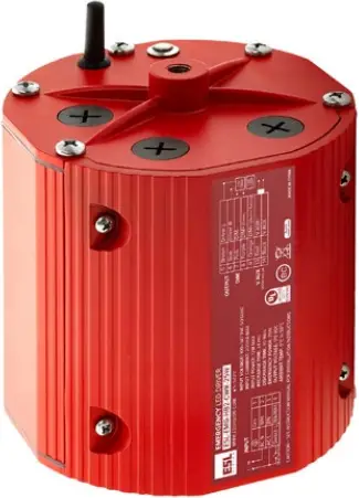
 LED EMERGENCY DRIVER
ESL-EMG-HB2-CWR-25W
Key Features & Benefits:
- Field or Factory Installation–UL 924 and CSA C22.2 No. 141 Emergency Lighting Compliant
- Meets CEC Title 20 Requirements.
- Monthly and Yearly Auto Test Function for Reduced Maintenance.
- Meets or Exceeds All NEC Emergency Lighting Standards.
- IP65 Wet Location Listed
- For Use with Round High Bay Fixture with Integrated 0–10V Drivers.
(See Wiring Diagrams for More Info) - Constant Power Output Provides 90 Minutes of Consistent Egress Lighting with No Degradation
Product Specifications:
Input
Rated Current: .2A (Max)
AC Input Power Rating: 12W
Rated Voltage: 100-347 VAC 50/60Hz
Output
Emergency Output Power: 25W (Max)
Output Voltage: 170 VDC
Emergency
Emergency Operation: 90 Minutes
Charging Time: 24 Hours
Charging Cycles: 1,000
Environment
Operating Temperature: 32° to 122°F (0° to 50°C)
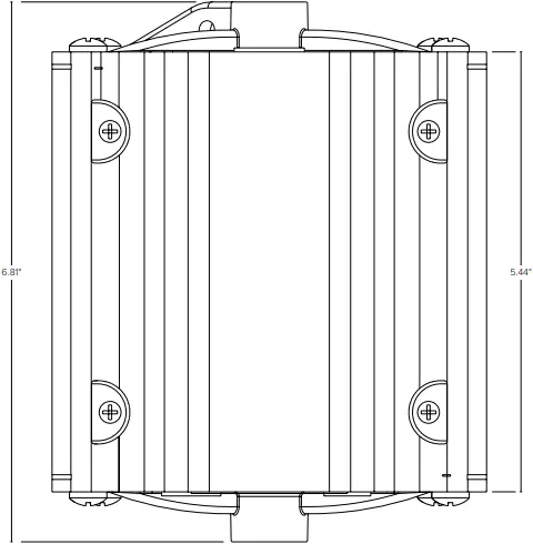
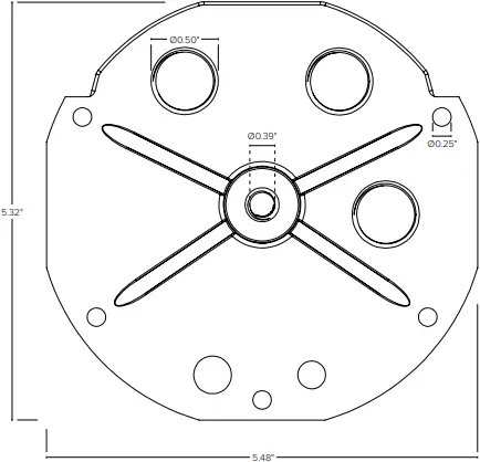
Dimensions (LxWxH): 5.47″ x 5.47″ x 5.55″
Mounting Length: 6.8″
Weight (lbs): 3.96
| Project: | Date: |
| Catalog #: | |
| Notes: | |

Ordering Guide:
|
ESL |
– | FAMILY | – | TYPE | – | FRAME | – | OUTPUT POWER |
| ESL | – | EMG | – | HB2 | – | CWR | – |
25W |
|
(EMG) Emergency |
(HB2) High Bay Gen 2 | (CWR) Closed Wet Rated |
(25W) 25 Watts |
Catalog Data:
|
ITEM# |
DESCRIPTION |
| ESL-EMG-HB2-CWR-25W | Emergency backup battery unit, auto test function, 25-watt output, 90-minutes minimum, 100–347 VAC input, 170 VDC output, closed cylinder, UL listed for factory or field install, Title 20. |
|
INCLUDED ACCESSORIES |
DESCRIPTION |
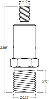
| ESL-EMG-HB2-CONNECT-RODM10 | Connecting rod M10 for EMG HB2 |
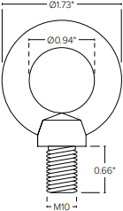
| ESL-ACCS-LOOP-M10 | Mounting loop for EMG HB2 |
| ESL-ACCS-HOOK-M10 | Mounting hook for EMG HB2 |
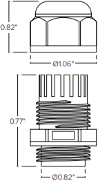
| ESL-ASMB-GLAND-PG11 | Nylon cable gland, black, PG11, 5-10mm OD wire |
Emergency Lumen Output:
|
FIXTURE EFFICACY |
OUTPUT POWER (15W) |
| 100 lm/W |
2,500 Lumens |
|
120 lm/W |
3,000 Lumens |
| 140 lm/W |
3,500 Lumens |
Operation (Indicator Status)
|
MODE |
TEST BUTTON OPERATION | INDICATOR STATUS |
SOLUTION |
| AC Mode (1) | NO Press | ON (no flashing) | Emergency LED driver is charging. |
| AC Mode (2) | Press Once | 2s ON and 2s OFF (slow flashing) | Emergency LED driver is conducting a 30s short-term emergency test. After 30 seconds, it will automatically return to normal charging mode. |
| AC Mode (3) | Press Twice (2s) in Sequence | 2s ON and 2s OFF (slow flashing) | Emergency LED driver is conducting a long-term emergency test until battery is fully discharged. |
| Emergency Mode | NO Press | 2s ON and 2s OFF (slow flashing) | Emergency LED driver is conducting a long-term emergency test until battery is drained of power. |
| Abnormal | When flashes ON (50ms) and OFF (50ms) fast, the emergency backup is abnormal. Contact the manufacturer. | ||
 WARNING
Risk of Electrical Shock
Note: Please press test button once to make certain the battery is turned off before installation, maintenance, storage or shipping.
Dimensions:
Loop Hook
ESL-ACCS-LOOP-M10 ESL-ACCS-HOOK-M10
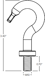
Wire Connector Connector
ESL-ASMB-GLAND-PG11 ESL-EMG-HB2-CONNECT-RODM10
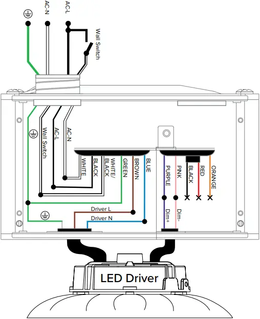
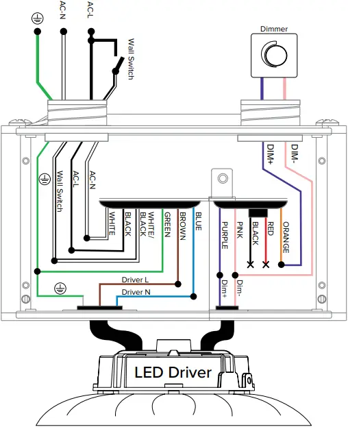
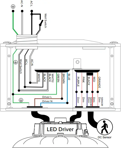
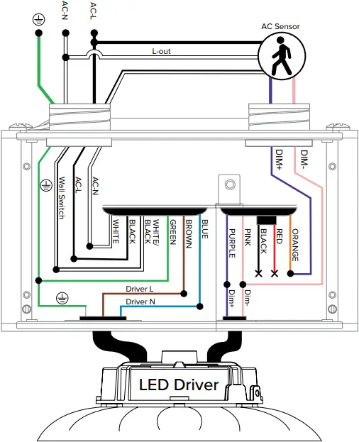
Wiring Diagrams:
Standard Installation
Dimmer Installation
DC Sensor Installation
AC Sensor Installation
Installation with KONEX Sensor

- EMG RHB AC Connecting line
- Core wire color: Red, Green, Black, Brown, Blue 5*18AWG, Wire outer diameter > 7.5mm
- External dimming line
- Core wire color: Red, Orange, Pink, Purple 4′ 24AWG, Wire outer diameter > 6mm
- Black To RCPA-WH DIM- (PNK)
Orange To RCPA-WH DIM+ (PUR)
Red To RCPA-WH DC12V (YEL) - Purple
Connect to Dim -(Driver)
Pink
Connect to Dim. (Driver) - Brown To Driver L
Blue To Driver N - Green To Drive and housing GND
Black To RCPA-WH L
White To RCPA-WH N - ESL-KNX-RCPA-WH
To AC Sensor
KNX-FS7,KNX-RPP-003 - WIRE COLOR KEY
Additional Materials:
- EMG RHB AC Connecting line
1.1 Open the power supply cavity of RHB1/2, remove the original 5FT 3 core wire, install it inside the EMG, and then lead out as AC.
1.2 Connect an EMG RHB AC Connecting line to the EMG and RHB.
For details, See the connection method in the picture. - External dimming line
2.1 Connect the 4-core External dimming line to the EMG and RHB.
See the connection mode in the figure. Note the color of the lead.
2.2 The black wire of the Sensor part of EMG is cut and not connected. The yellow cable of the Driver is cut and not connected.
Pay attention to insulation treatment. - Connecting terminal Add a part of P4/WAGO for wire connection.
- Use of KNX/Sensor:
4.1 RPP-003: Use APP / 3BS-01WH or FS7 of the same group to turn off the luminaires
4.2 KNX-FS7 : Use APP / 3BS-01WH or FS7 of the same group to turn off the luminaires
Copyright © 2024 ESL Vision, LLC. All rights reserved. Rev: 03/12/24
 888.493.5559
  [email protected]
  www.eslvision.com