Contents
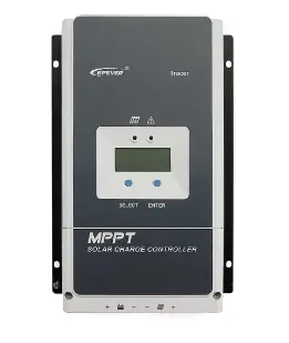
EPEVER Tracer 7810CPN MPPT Solar Charge Controller User Manual
Thank you for selecting the Tracer-CPN MPPT solar charge controller. Please read this manual carefully before using the product and pay attention to the safety information.
※ Do not install this product in humid, salt spray, corrosion, greasy, flammable, explosive, dust accumulative, or other severe environments.
MPPT Solar Charge Controller
Overview
The Tracer-CPN solar charge controller adopts the advanced Maximum Power Point Tracking charging technology. Increase the system charging efficiency yet lower the system cost. The controller supports various batteries, such as sealed, gel, flooded, and lithium batteries. Users can view and modify the operational status and parameters. It can be widely used in a solar home system, traffic signal, street light, solar garden lamp, etc. The features are listed below:
- Adopt high-quality components of ST, IR, and Infineon to ensure product lifespan
- Wider working environment temperature
- Apply to lead-acid battery and lithium battery
- Lithium battery self-activating and low-temperature protection function
- The maximum DC/DC conversion efficiency of 98%
- Advanced Maximum Power Point Tracking (MPPT) technology, with tracking efficiency of no less than 99%
- Advanced MPPT control algorithm to minimize the MPP lost rate and lost time
- Accurately recognizing and tracking multiple power points
- PV power limitation function
- Constant voltage output function
- Monitoring and setting parameters via Mobile APP, PC software
- Standard Modbus communication protocol for the RS485 bus connections
- Connect the IoT (Internet of Things) and Cloud Server to realize remote monitoring
- The RS485 port can provide a power supply
- Built-in Bluetooth module (Only Tracer-CPN(BLE) supports)
- Low self-consumption design, lower than 15mA
- Aluminum housing for better cooling
- Real-time energy statistics function
- IP68 waterproof degree
Appearance
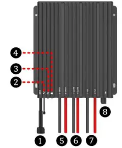
| ① | RS485 waterproof port⑴ |
| ② | Temperature Sensor⑵ |
| ③ | Charging Status indicator |
| ④ | Battery Status indicator |
| ⑤ | Load Positive and Negative Wires |
| ⑥ | Battery Positive and Negative Wires |
| ⑦ | PV Positive and Negative Wires |
| ⑧ | Built-in Bluetooth module⑶ |
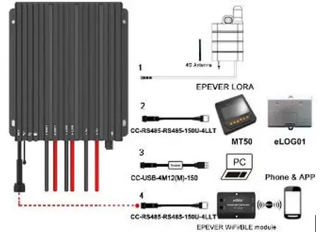
⑴ The RS485 waterproof port can provide a DC power of 5VDC/200mA, and have the short-circuit protection function. The port is isolation design for Tracer7810CPN/ Tracer7810CPN(BLE), and non-isolation design for other series. The pin definition is shown below:
| Pin | Definition |
| VCC | +5VDC |
| A | RS485-A |
| B | RS485-B |
| GND | Power ground |
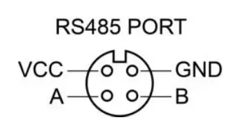
CAUTION: When the RS485 port is not working, the waterproof cap must be installed to prevent water from getting in.
⑵ If the temperature sensor is short-circuited or damaged, the controller shall be charging or discharging at the default temperature of 25℃.
⑶ Only the Tracer-CPN (BLE) series are designed with the built-in Bluetooth module; please select as you require.
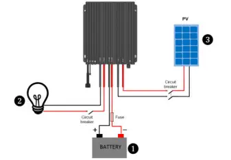
Wiring
l Connection sequence
- Connect components to the controller in the sequence ①Battery > ②load > ③PV as shown above and pay much attention to the “+” and “-.” Please don’t connect the fast-acting fuse or circuit breaker during the installation. When disconnecting the system, the order will be reserved.
- The Tracer-CPN/Tracer-CPN (BLE) controllers are common-negative; all the negative terminals can be grounded simultaneously, or anyone can be However, according to the practical application, the negative terminals of the PV array, battery, and load can also be ungrounded. Still, the grounding terminal on the shell must be grounded. It effectively shields electromagnetic interference from the outside and prevents some electric shock to the human body.
 A common-negative controller for a common-negative system, such as the motorhome, is recommended. The controller may be damaged if a common-positive controller is used and the positive electrode is grounded in the common-negative system.
) Connect a fast-acting fuse in series with the battery positive (+). The fast-acting fuse must be 1.25 to 2 times the rated controller current. The installed distance is within 150mm.
4) After powering the controller, the battery LED indicator on the controller shall flash green. If it’s not green, please refer to chapter 10, Troubleshooting.
l Loadself-testfunction
TheloadisautomaticallyturnedONafterpoweringonthecontrollerfor10s.AftertheloadkeepsONstatusfor10s,thecontroller restorestothe setworkingmode.
LED Indicators
| Indicator | Color | Status | Instruction |

|
Green |
On Solid |
PV connection normal but low voltage(irradiance) from PV,
no charging |
| OFF | No PV voltage(night time) or PV connection problem | ||
| Slowly Flashing(1Hz) |
In charging |
||
| Fast Flashing(4Hz) | PV overvoltage | ||

|
Green |
On Solid | Battery normal |
| Slowly Flashing(1Hz) |
Battery full |
||
| Fast Flashing(4Hz) | Battery overvoltage | ||
| Orange | On Solid | Battery under voltage | |
|
Red |
On Solid | Battery over-discharged | |
|
Fast Flashing(4Hz) |
Battery overheating Lithium battery low
temperature |
||
| Charging indicator(green) and battery indicator(orange) flashing simultaneously | System voltage error※ | ||
When connecting with a lithium battery, the controller does not recognize the system voltage automatically.
Load Working Mode
1) Manual Mode (Default ON)
2 Light ON/OFF

Turn-On voltage (Adjustable): 5V (12Vsystem), delay10min. Turn-Off voltage (Adjustable): 6V (12Vsystem), delay10min. Note: 24V system voltage×2
4) Real-time Control
Control the load ON/OFF time by setting a real-time clock.
1) PC Software
www.epever.com ——Solar Station Monitor
2) APP Software
- Android phone
www.epever.com——ChargeController(Li)
- iPhone
APP Store——EPEVER——EP-01
MT50 does not support the relevant parameters of the lithium battery.
Protection
PV Over Current
The controller will limit the battery charging current to the rated charge current. Therefore an oversized solar array may not work at peak power.
PV Short Circuit
The controller will stop charging when the PV input is short-circuited or the short-circuit occurs at the low-power charging. Clear faults to resume work.
PV Reverse Polarity
The PV can be reversely connected with a controller when:
①Only the PV is connected to the controller. ②The battery is correct connected, and the PV open-circuit voltage is lower than 85V.
Battery Reverse Polarity
|
The battery can be reversely connected when the PV is disconnected or reversely connected. Correct the wire connection to resume work.
Battery Over Voltage
When the battery voltage exceeds the Over Voltage Disconnect Voltage, the controller will stop charging the battery to protect the battery from being overcharged.
Battery Over Discharge
When the battery voltage is lower than the Low Voltage Disconnect Voltage, the controller will stop discharging the battery to protect the battery from being over-discharged.
Battery Overheating
The controller detects the environment temperature by the external temperature sensor. If the environment temperature exceeds 65ºC, the controller will stop working and recover below 55ºC.
Lithium battery Low Temperature
When the battery temperature is lower than the low-temperature protection value, the Lithium battery charging/discharging is stopped. It resumes work when the battery temperature exceeds the low-temperature protection value.
Load Overload
If the load current exceeds 1.05 times the rated load current, the controller will
disconnect the load after a delay time. Overloading must be cleared by reducing the load and restarting the controller.
Load Short Circuit
The load will be switched off when the short circuit (≥4 times rated load current) happens. The controller will automatically attempt to reconnect the load five times. Suppose short circuit protection still exists after the fifth attempt. In that case, the user has to clear the short circuit, restart the controller or wait for one night-day cycle (night time>3 hours).
Temperature sensor breakdown
When the temperature sensor is short-circuited or damaged, the controller will charge or discharge at 25°C by default to avoid damage to the battery caused by overcharge or over-discharge.
High-voltage Transients
The controller is protected against small high-voltage transients. In lightning-prone areas, additional external arrester is recommended.
Troubleshooting
| Faults | Possible reasons | Troubleshooting |
| Charging LED is off during the daytime,
and sunshine falls on PV modules properly |
PV array disconnection |
Confirm that PV and battery wire connections are correct and tight |
|
No LED indicator |
Battery voltage may be less than
8.5V |
Measure battery voltage with the multi-meter. A minimum of 8.5V can
start up the controller |
| Battery LED flashes green quickly | Battery over voltage | Check if the battery voltage exceeds the OVD, and disconnect the PV |
|
Battery LED is red ON solid |
Battery over-discharged |
The load will recover when the battery voltage is restored to or
above the LVR (low voltage reconnect voltage). |
| Battery LED flashes red | Battery Overheating | The controller will resume when the battery temperature declines to 50ºC or below. |
|
The load has no output |
① Load Overload |
①Please reduce the number of electric equipment.
②Restart the controller. ③wait for one night-day cycle (night time>3 hours). |
|
Load Short Circuit ① |
①Check carefully the loads’ connection and clear the fault.
②Restart the controller. ③wait for one night-day cycle (night time>3 hours). |
When the load is overloaded or short-circuited, the load will automatically restore output five times, respectively, delaying 5S, 10S, 15S, 20S, and 25S.
Disclaimer
This warranty does not apply to the following conditions:
- Damage from improper use or use in an unsuitable
- PV or load current, voltage, or power exceeds the rated value of the
- The actual working temperature exceeds the limited working environment
- The user disassembly or attempted to repair the controller without
- The controller is damaged due to natural elements such as
- The controller is damaged during transportation and
Technical Specifications
| Item Model | Tracer5206CPN/Tracer5206CPN(BLE) | Tracer7810CPN/Tracer7810CPN(BLE) | |
| Rated system voltage | 12/24VDC Auto( Lithium battery cannot automatically identify system voltage) | ||
| Battery work voltage range | 8 ~ 32VDC | ||
| Rated charge/discharge current | 20A | 30A | |
| Rated charge power | 260W/12V; 520W/24V | 390W/12V; 780W/24V | |
| Max. PV open circuit voltage | 60V (at minimum operating environment temperature)
46V( at 25℃ environment temperature ) |
100V (at minimum operating environment temperature)
92V( at 25℃ environment temperature ) |
|
| MPP Voltage range | (Battery voltage +2V) ~ 36V | (Battery voltage +2V) ~ 72V | |
| Battery Type | Lead-acid battery: Sealed(Default) / Gel / Flooded/User; Lithium battery:LiFePO4/ Li-NiCoMn/User | ||
| Lead-acid | Equalize Charging Voltage | Sealed: 14.6V, Gel: No, Flooded: 14.8V, User: 9-17V (×2/24V) | |
| Boost Charging Voltage | Sealed: 14.4V, Gel: 14.2V, Flooded: 14.6V, User: 9-17V (×2/24V) | ||
| Float Charging Voltage | Sealed/Gel/Flooded: 13.8V, User: 9-17V (×2/24V) | ||
| Low Voltage Reconnect Voltage | Sealed/Gel/Flooded: 12.6V, User: 9-17V (×2/24V) | ||
| Low Voltage Disconnect Voltage | Sealed/Gel/Flooded: 11.1V, User: 9-17V (×2/24V) | ||
| Lithium | Boost Charging Voltage | LiFePO4: 14.5V, Li-NiCoMn: 12.5V, User: 9-17V (×2/24V) | |
| Low Voltage Reconnect Voltage | LiFePO4: 12.8V, Li-NiCoMn: 10.5V, User: 9-17V (×2/24V) | ||
| Low Voltage Disconnect Voltage | LiFePO4: 11.1V, Li-NiCoMn: 9.3V, User: 9-17V (×2/24V) | ||
| Self-consumption | ≤10mA(12V); ≤7mA(24V) | ≤15mA(12V); ≤9mA(24V) | |
| Temperature compensation coefficient | -3mV/℃/2V (Lithium batteries don’t have temperature compensation coefficient) | ||
| Communication | RS485/BLE | ||
| Work temperature | -40℃~+50℃ (Above 45℃, please operate in derating) | ||
| Enclosure | IP68 | ||
|
Dimension (L x W x H) |
Tracer5206CPN: 147mm × 130mm × 50mm Tracer5206CPN(BLE): 157mm × 130mm × 50mm | Tracer7810CPN: 155mm × 141mm × 51.5mm Tracer7810CPN(BLE): 165mm × 141mm × 51.5mm | |
| Mounting hole size | Φ4.5mm | Φ4.5mm | |
| Mounting size (L x W) | 121mm × 120mm | 132mm × 120mm | |
| Power cable (PV/BAT/LOAD) | PV:11AWG, BAT/LOAD: 10AWG | PV:11AWG, BAT/LOAD: 10AWG | |
| Net weight | 1.30kg | 1.59kg | |
Any changes without prior notice! Version number: V1.1