![]() EC18006, EC18007 Florence Screen Kit with Planter Box
EC18006, EC18007 Florence Screen Kit with Planter Box
Instruction Manual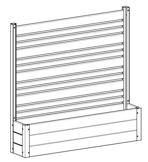
Contents
EC18006, EC18007 Florence Screen Kit with Planter Box
Florence Screen Kit W/ Planter Box
![]() 45 min Approximate assembly time for 1 screen
45 min Approximate assembly time for 1 screen
![]() Scan the QR code for an assembly video
Scan the QR code for an assembly video
 ASSEMBLY INSTRUCTIONS
EC18006 (CEDAR COLOR) EC18007 (ASH COLOR)
GENERAL INFORMATION
IMPORTANT
- Check the inside of the larger pieces in your box for other materials packed inside.
- When assembling components, place on a non-abrasive surface (i.e. shipping box) to avoid scratching.
- We recommend an area approximately 5’x 8’ for unobstructed assembling.
- You should not need to use excessive force when assembling components.
MISSING OR DAMAGED PARTS?
VISIT OUR WEBSITE FIRST, SO WE CAN HELP YOU RIGHT AWAY!
Although great care has been taken to ensure proper packaging and handling of this product, occasionally problems occur. If you discover any missing, damaged, or defective parts, please visit our website to order replacement parts. If you experience any further trouble with your product, please contact our customer service department.
parts.nychbrands.com
[email protected]
704-892-5222 / 877-234-6196
Customer service agents are available to take calls weekdays from 9am-5pm EST. If you call outside of business hours, please leave a voicemail.
To help you quickly and accurately, please have reference item number EC18006/EC18007 and the specific part name which can be found on page 4. It is helpful if you can provide the batch lot which is a stamped number on the end of the box.
NEED ASSEMBLY HELP?
If you are having problems with the assembly or installation of this product, we are happy to assist you with the process, so please give us a call at 704-892-5222 / 877-234-6169
NEED TO RETURN?
If for some reason you need to return this product, please allow us to help resolve your issues first. If you still decide to return the product, you will need to initiate the return from the company you originally purchased from.
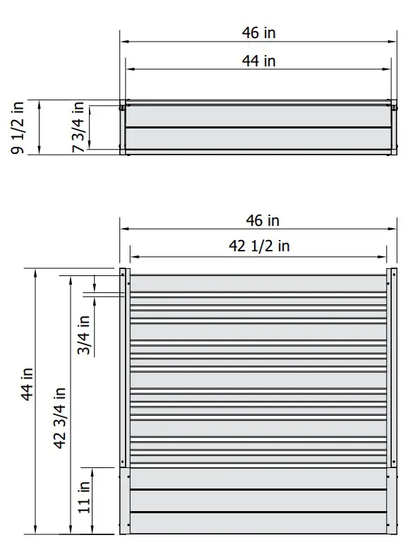
Detailed Product Dimensions & Specifications
 STEP 1: LAY OUT MATERIALS
 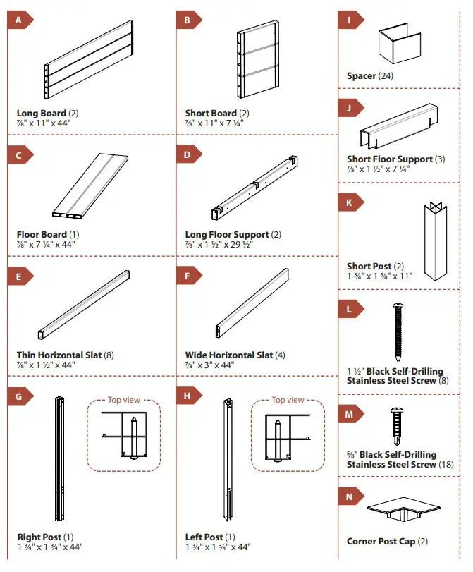 STEP 2: ASSEMBLING BOARDS
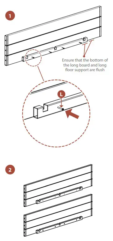
STEP 2.1
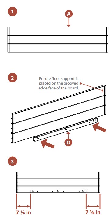
- Lay down (1) Long Board (A) so that the cut grooves face up as shown.
- Place (1) Long Floor Support (D) at the bottom of the long board.
- Position the long floor support so it rests in the middle of the long board.
 STEP 2.2
- Drive (4) 11/2″ Black Self-Drilling Stainless Steel Screws (L) into the predrilled holes in the long floor support.
- Repeat these steps for the second long board.
 STEP 3: ASSEMBLING THE PLANTER BOX
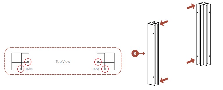
STEP 3.1
- Orient (2) Short Posts (K) as shown, with two post channels facing each other, and twochannels facing front.
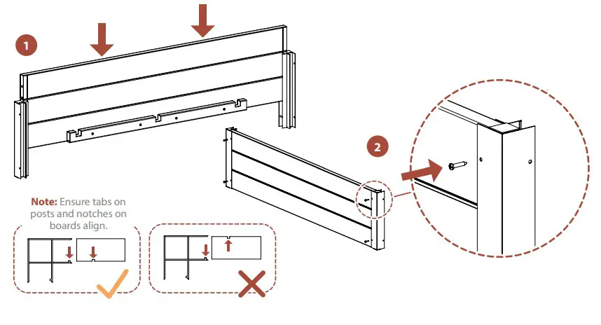
 STEP 3.2
- Slide (1) long board into the post channels, ensuring that the tabs on the posts align with the grooves in the board.
- Drive (4) 5/8″ black self-drilling stainless steel screws (M) into the predrilled holes in the posts, securing the long board.
Note: Ensure the bottom of the board is flush to the bottom of the posts.![]()
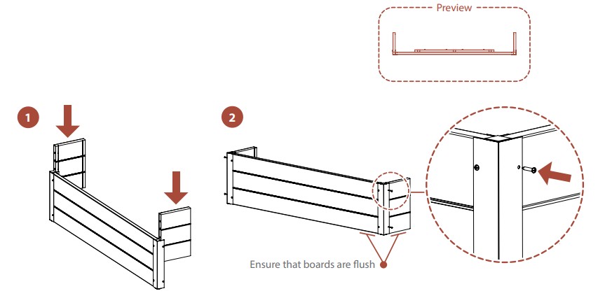
 STEP 3.3
- Slide (2) Short Boards (B) into the short post channels, ensuring that the board bottoms are flush. Drive (4) 5/8″ black self-drilling stainless steel screws into the
pre-drilled holes in the sides of the short posts.
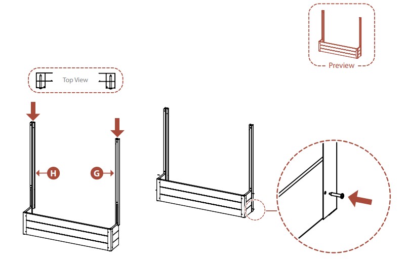
 STEP 4: INSTALLING REAR POSTS
STEP 4.1
- Slide (1) Right Post (G) and (1) Left Post (H) over the short boards so that the partially covered channel on each post faces the front.
- Drive (4) 5/8″ black self-drilling stainless steel screws into the pre-drilled holes in the sides of the posts.
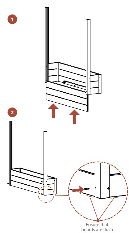
 STEP 5: COMPLETING PLANTER BOX
STEP 5.1
- Slide the second long board into the post channels. Ensure that this board rests flush with the other boards.
- Drive (4) 5/8″ black self-ruling stainless steel screws into the predrilled holes in the posts.
![]()
 STEP 5.2
- Fit (3) Short Floor Supports (J) so that the notches fit over the inner walls of the long floor upports as shown.
- Place (1) Floor Board (C) into the planter box, so it rests on the floor supports.
![]() Note: For best plant growth, it is recommended to drill (2) 3/4″ diameter drainage holes in the floor board roughly 12″ apart.
Note: For best plant growth, it is recommended to drill (2) 3/4″ diameter drainage holes in the floor board roughly 12″ apart. 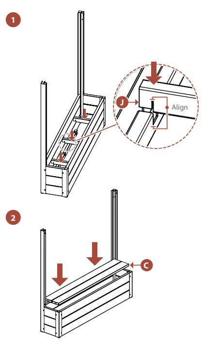 STEP 6: ASSEMBLE THE SCREEN
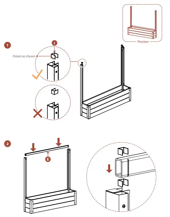
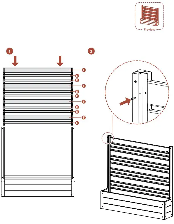
STEP 6.1
- Insert (1) Spacer (I) into both the left and right post channel in the orientation shown below. This will create even spacing between the horizontal slats.
- Slide (1) Thin Horizontal Slat (E) into the post channels.
 STEP 6.2
- Slide (7) additional thin horizontal slats, (4) Wide Horizontal Slats (F) and (11) aluminum spacers into the post channels in the pattern shown below. Spacers should be inserted between each horizontal slat.
- Drive (2) 5/8″ black self-drilling stainless steel screws into the pre-drilled holes in the posts, securing the top horizontal slat.
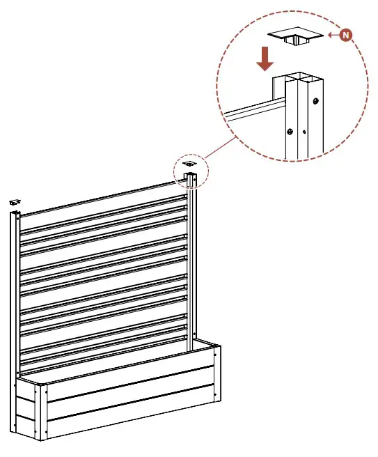
 STEP 7: INSTALL POST CAPS
STEP 6.1
- Insert the (2) Corner Post Caps (N) into the holes in the top of the posts to finish the assembly.
![]() www.encloscreens.com
www.encloscreens.com
![]() [email protected]
[email protected]
![]() 704-892-5222
704-892-5222
877-234-6196
![]() 6935 Reames Rd. Ste. K.
6935 Reames Rd. Ste. K.
Charlotte, NC 28216
ASSEMBLY
INSTRUCTIONS
EC18006 (CEDAR COLOR)
EC18007 (ASH COLOR)