Contents
ELKAY ENLZSTL8WS_1G_PIVOT TM Series Bottle Filling Stations and Coolers
Specifications
- Model: ENLZSTL8WS_1G_PIVOT
- Series: LZ TM Series
- Installation: Versatile design allows for flexible installation
- Cooler Placement: Must be hung on the right side
Product Usage Instructions
- Standard Rough-In for Left-Hand High, Bottle Filler Low Models:
Instructions for standard rough-in installation… - Alternate Rough-In for Left-Hand Low, Bottle Filler High Models:
Instructions for alternate rough-in installation…
FAQ
- Q: Can the cooler be installed in any orientation?
A: No, the refrigerated coolers must be hung on the right side as specified in the manual. - Q: Do I need to change the basin for installation?
A: Depending on the desired rough-in configuration, a basin change may be required. Refer to the manual for guidance.
Enhanced
INSTALLATION & USE MANUAL
LZ ™ Series Bottle Filling Stations & Coolers
*Versatile cooler design allows units to be installed either left-hand high and right-hand low or left-low and right high. Basin change may be required. See desired rough-in to help determine if the basin change is necessary.
Important: The refrigerated coolers must be hung on the right side. Patent zurn-elkay.com/patents
WARNING: Cancer and Reproductive Harm – www.P65Warnings.ca.gov
STANDARD ROUGH-IN FOR LEFT-HAND HIGH, BOTTLE FILLER LOW MODELS
 REDUCE HEIGHT BY 3 INCHES FOR INSTALLATION OF CHILDREN’S ADA COOLER
LEGEND
- A = RECOMMENDED WATER SUPPLY LOCATION 3/8 O.D. UNPLATED COPPER TUBE CONNECT STUB WITH SHUT OFF (BY OTHERS) 3 IN. (76mm)
MAXIMUM OUT FROM WALL - B = RECOMMENDED LOCATION FOR WASTE OUTLET 1-1/2″ O.D. DRAIN STUB 2 IN. OUT FROM WALL
- C = 1-1/2″ TRAP NOT FURNISHED
- D = ELECTRICAL SUPPLY (3) WIRE RECESSED BOX DUPLEX OUTLET**
- E = INSURE PROPER VENTILATION BY MAINTAINING 6″ (152 mm) (MIN.) CLEARANCE FROM CABINET LOUVERS TO WALL.
- F = 7/16 BOLT HOLES FOR FASTENING UNIT TO WALL
**NEW INSTALLATIONS MUST USE GROUND FAULT CIRCUIT INTERRUPTER (GFCI)
ALTERNATE ROUGH-IN FOR RIGHT-HAND HIGH, BOTTLE FILLER LOW MODELS – REQUIRES BASIN ASSY CHANGE

ALTERNATE ROUGH-IN FOR LEFT-HAND LOW, BOTTLE FILLER HIGH MODELS

ALTERNATE ROUGH-IN FOR RIGHT-HAND LOW, BOTTLE FILLER HIGH MODELS – REQUIRES BASIN ASSY CHANGE

INSTRUCTIONS FOR REMOVING WRAPPER

- Remove the two security screws from the front panel. (see Fig D(i)).
NOTE: SCREW THREADS INTO BUSHING WHILE ANGLED. DO NOT ATTEMPT TO THREAD SCREW INTO BUSHING HORIZONTALLY. - Gently pull the wrapper down and rotate the wrapper to a downward position (see Fig D(ii).
- To remove the wrapper, hold each side and gently pull wrapper up and out of pivoting bracket (see Fig D(iii)).
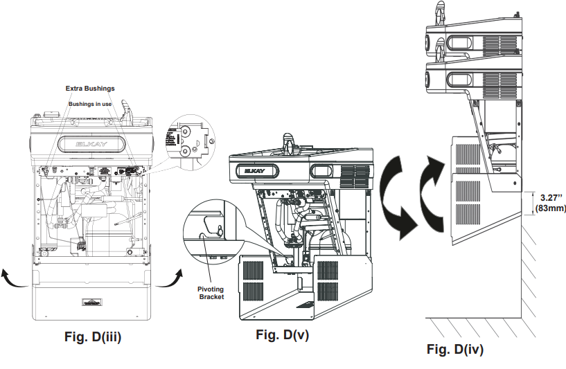 CAUTION: WRAPPER DROPS AND SWINGS WHEN SECURITY SCREWS ARE REMOVED.
CAUTION: DO NOT LEAN ON WRAPPER.
CAUTION: DO NOT USE POWER TOOL TO TIGHTEN. DO NOT OVERTIGHTEN.
NOTE
- Ensure that there are no plumbing or external objects below the wrapper in the specified dimension.
The specified (3.27’’) minimum distance is required for the wrapper to swing out (see Fig D(iv)). - Removing the wrapper from the pivoting bracket when servicing the unit is recommended. The wrapper may be left in place for quick serviceability (see Fig D(iii)).
- When re-attaching wrapper, ensure each side of wrapper is engaged to pivoting bracket (see Fig D(v)).
- Once the wrapper is in place, rotate wrapper up and under the shroud. Ensure thru holes on wrapper are aligned with plastic bushing threads on the frame prior to engaging security screws. Ensure screw is angled relative to the ground and perpendicular to wrapper surface prior to engagement. Hand tighten prior to using hand tool to avoid cross-threading.
- Four plastic bushings are located in the cross brace of the frame. The lower two bushings align with wrapper holes and the top two bushings are extras in case of replacement (see Fig D(iii)).
NOTE:
The highlighted portion in red color is acceptable plumbing rough-in for installation.
NOTE
To mitigate the wrapper rotation interferences, zip tie lines (plumbing and electrical) running between the cooler units to the waste line (PVC pipe).
HANGER BRACKETS INSTALLATION
- Remove hanger bracket fastened to back of coolers by removing one (1) screw.
- Determine your mounting configuration from the figures shown on pages 2 – 5. Refrigeration unit must be on right hand side. IMPORTANT NOTE: If the Bottle Filler is to be mounted on the left hand cooler, a basin assembly change will be needed. Determine your configuration by referring to the Configuration Instructions on page 10 prior to continuing.
- Mount the hanger bracket as shown in Figures 1 – 4 (Pages 2 – 5).
NOTE: Hanger Bracket MUST be supported securely. Add fixture support carrier if wall will not provide adequate support. Anchor hanger securely to wall using all six (6) 1/4 in. dia. mounting holes.
IMPORTANT: 5-7/8 in. (150 mm) dimension from wall to centerline of trap must be maintained for proper fit.
INSTALLATION OF COOLER - Refer Fig D(i) to D(iv), Pg. 6 for wrapper removing instructions.
- Hang only the refrigerated cooler on the hanger bracket. Be certain hanger bracket is properly in the slots on the cooler backs as shown in Figures 1 (Pg. 2), 2 (Pg.3), 3 (Pg. 4), and 4 (Pg. 5).
- Hang the non-refrigerated cooler on the hanger bracket. Be certain hanger bracket is engaged properly in the slots on the cooler backs as shown in Figures 1 (Pg. 2), 2 (Pg. 3), 3 (Pg. 4), and 4 (Pg. 5).
- Unband the loose wires in the refrigerated cooler for the filter communication board. Stretch it out and thread through the left side of the refrigerated cooler and into the right side of the non-refrigerated cooler. Plug into the filter communication board that is behind the filter head.
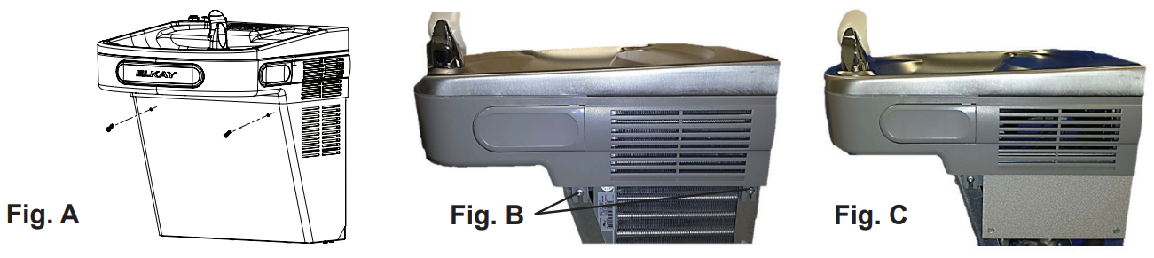
- Secure each cooler frame to wall by installing (2) screws and washers (not supplied) in lower holes. See pictures below.
Make sure the screws engage in a structural member.  Connect the supply water to the filter 3/8” copper inlet tube.
- Connect the waterline from the outlet of the filter to the inlet of the evaporator in the refrigerated cooler by inserting it into the quick connector.
- Connect the waterline from the solenoid in the non-refrigerated cooler to the open 1/4” inch tee fitting in the refrigerated cooler.
- Find your cooler configuration on page 11 and connect the drain assembly together.
- Install trap.
IMPORTANT: If it is necessary to cut the drain, loosen the screw at the black rubber boot and remove tube, check for leaks after re-assembly.
BOTTLE FILLER INSTALLATION - Remove two (2) mounting screws with 5/32” Allen wrench holding Bottle Filler to wall mounting plate (See Fig. 8). Note do not discard mounting screws, they will be needed to secure Bottle Filler to wall mounting plate.
- Remove wall mounting plate from Bottle Filler (See Fig. 8 ). Place wall mounting plate against wall on top of basin. Center the wall mounting plate side to side with the basin. Mark the six (6) mounting holes with a pencil (See Fig. 1, Pg. 2). Place tape over wiring harness connection on top of cooler to prevent debris from falling into Connection(See Fig. 6, Pg. 7).
- Remove wall mounting plate from wall. NOTE: Mounting plate MUST be supported securely. Add fixture support carrier if wall will not provide adequate support.
- Install wall mounting plate to wall using six (6) 7/16” obround mounting holes (mounting
bolts not included) (See Fig. 7, Pg. 7). Use appropriate fasteners for your wall type. - Install gasket on bottom of Bottle Filler with gasket support bracket & (2) screws. (See Fig. 8).
 Route 3/8” tubing through the opening in the bottle filler gasket and plug into bulkhead fitting in basin. Route the wiring harness through the gasket and plug into the connector on the top of the basin. Water line should be cut to length prior to attaching to bulkhead fitting.
- Place Bottle Filler on the four (4) hooks on the mounting plate installed on wall.

 FINAL INSTALLATION (FILTER)
 - Remove filter from carton, remove protective cap, attach filter to filter head by firmly in-serting into head and rotating filter clockwise. Ensure that front facing label can be read when filter is installed. (See Fig. 12)
- Turn water supply on and inspect for leaks. In both cooler and Bottle Filler. Fix all leaks before continuing.
- Once cooler and bottle filter have been inspected for leaks and any leaks corrected, plug cooler into wall.
- Reinstall two mounting screws from first step above. Caution do not over tighten screws.
- Once power is applied to the cooler the GREEN LED light will illuminate on the bottle filler showing good filter status along with the LCD Bottle Counter.
- Verify proper dispensing by placing cup, hand, or any opaque object in front of sensor area and verify that the water dispenses. Note: the first initial dispenses might have air in line which may cause a sputter and hazy appearance. Run water and flush filter to purge air and fine carbon particles from filter before use. This will be eliminated when all air is purged from the line.
- Once unit tests out, install Lower Panels back on water coolers. (See pages 12-13 for versatile wrapper installation).
- When re-attaching wrapper, push wrapper up and under the shroud. Make sure wrapper and bushing holes are aligned prior to inserting screw. Units are now ready for use.

INSTRUCTIONS FOR REPLACING FILTERS
- Refer Fig D(i) to D(iv), Pg. 6 for wrapper removing instructions.
- Turn off water supply; dispense water to relieve pressure.
- Remove power by unplugging cooler.
- Turn used filter counterclockwise 1/4 turn to remove from filter head.
- Remove cap from new filter and use to seal used filter.
- Insert new filter into existing filter head and turn fully clockwise. Make sure you can read the label on the front of the filter once it is installed.(See Fig. 12).
- Plug in unit to restore power.
- Turn on water supply and run water and flush filter to purge air and fine carbon particles from filter before use. Visit elkay.com/filtration for additional details. Also run water through bottle filler until all air is removed and water flow is clear.
Note: Filter status light will automatically reset once new filter is installed.
INSTRUCTIONS TO ACCESS PROGRAMMING BUTTON
- Remove lower cover on refrigerated unit by removing (2) screws.
- Button is located in lower right corner of unit (See Fig. 13).

CONFIGURATION INSTRUCTIONS
INSTRUCTIONS TO MOVE THE BOTTLE FILLER & BASIN TO THE LEFT SIDE (NON-REFRIGERATED) FOR ALTERNATE MOUNTING VERSATILE BI-LEVEL

- Refer Fig D(i) to D(iv), Pg. 6 for wrapper removing instructions.
- Remove fi ller panel from cooler using a 5/16” socket.
- Using a T25 (6-point star) bit, loosen the shroud screws on both sides of both coolers.
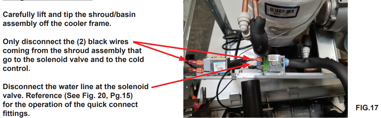
- Lift the basin/shroud assembly from each cooler. Disconnect the water line from the solenoid and the shroud wires from the wiring harness and solenoid. Set aside.
- Unfasten the electrical harness connector from the electrical bracket.
Using a T25 (6-point star) bit, remove the electrical bracket from the mounting bracket. Snap the electrical harness connector into the cutout of the mounting bracket with the connector facing down. (See Fig 14.)
- Install the electrical bracket on the fi lter bracket of the non-refrigerated cooler by removing the two screws towards the front of the cooler and reinstalling them through the bracket. Attach the female end of the bi-level extension into the electrical bracket.
- Only move the fi ller panel and J-clip to the refrigerated (right) cooler if the right side will be mounted high.
- Install the non-bottle fi ller basin on the refrigerated cooler. Connect the water line
to the solenoid and the electrical connections to the wiring harness and solenoid. Tighten the (4) T25 screws. - Mount the refrigerated cooler on the right-hand hanger bracket. Secure to wall.
- Install the bottle fi ller basin on the non-refrigerated cooler. Connect the water line to the solenoid and the electrical connections to the wiring harness and solenoid. Be certain the electrical connector is protruding through the cutout in the top of the basin. Tighten the (4) T25 screws.
- Mount the non-refrigerated cooler on the left-hand hanger bracket. Secure to wall.
- Route the bi-level extension through the coolers and connect to the refrigerated electrical harness mounted in the mounting bracket (See Figs. 15 & 16).

- Hook up the drains using the attached drain kit.
- Make all water and electrical connections.
- Reinstall wrappers using (2) screws for each wrapper.
Refrigerated Cooler side:
Non-Refrigerated Cooler side

Swap drain parts in shroud: Loosen each hose clamp retaining the drain pieces. Remove each drain piece and swap to other basin. Tighten each hose clamp.
Enhanced EZH2O Error Codes
PLUMBING DIAGRAMS VERSATILE BI-LEVEL

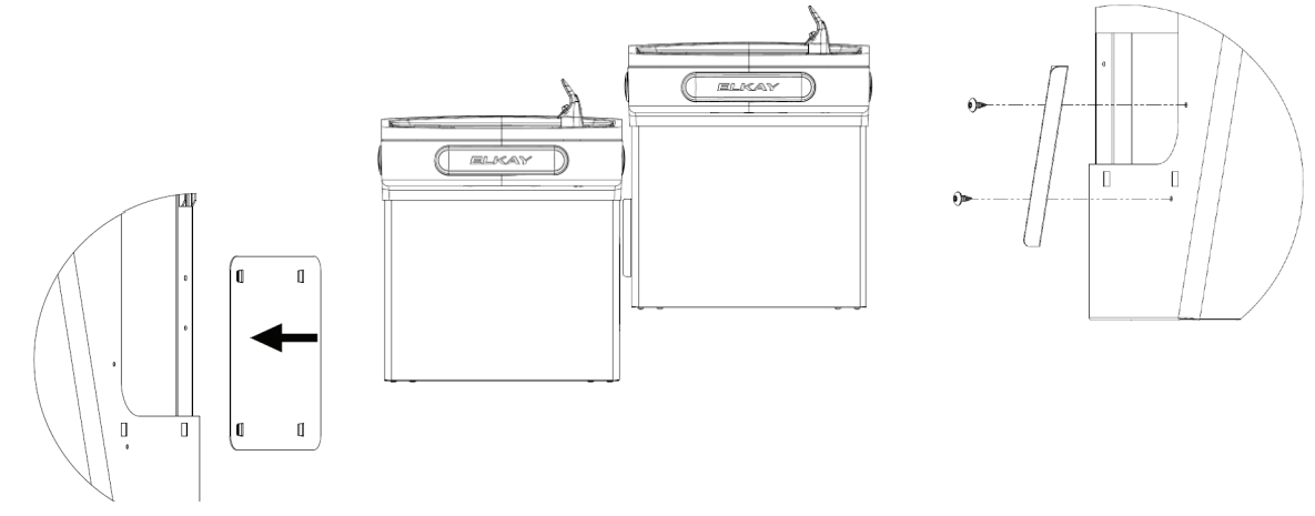
Versatile Wrapper and Trim Kit Installation Instructions
Left Hand Wrapper (High Side)
- Remove the (2) screws from the wrapper, rotate the wrapper down, and remove.
- Screw trim piece to wrapper with (2) screws (provided).
- Re-install wrapper with (2) screws.
- Dispose of unused cover plate.

Right Hand Wrapper (Low Side)
- Remove the (2) screws from the wrapper, rotate the wrapper down, and remove.
- Clip cover plate, sliding until plate sits flush with the wall.
- Re-install wrapper with (2) screws.
- Dispose of unused trim piece.

 Left Hand Wrapper (Low Side)
- Remove the (2) screws from the wrapper, rotate the wrapper down, and remove.
- Clip cover plate, sliding until plate sits flush with the wall.
- Re-install wrapper with (2) screws.
- Dispose of unused trim piece.
Right Hand Wrapper (High Side)
- Remove the (2) screws from the wrapper, rotate the wrapper down, and remove.
- Screw trim piece to wrapper with (2) screws (provided)
- Re-install wrapper with (2) screws.
- Dispose of unused cover plate.

115V Refrigerated Wiring Diagram with Alpha/Numeric Display

OPERATION OF QUICK CONNECT FITTINGS

NOTE
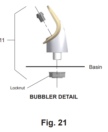
When installing replacement bubbler and pedestal, tighten nut only to hold parts snug in position. Do Not Overtighten.
WATERSENTRY® Filter Detail
| WATERSENTRY® FILTER PARTS LIST | ||
| ITEM NO. | PART NO. | DESCRIPTION |
| 1 | 51300C | Filter 3000 Gal (standard) |
| 2 | 51600C | Filter 6000 Gal (high capacity) |
| 3 | 71300C | Filter 2250 Gal (PFOA/PFAS) |
| 4 | 1000005214 |
|
| Filter Bracket/Screws | ||
| 5 | 1000004409 | Kit – NFC Board/Cover |
Service Instructions
- Lower and Upper Shroud
To access the refrigeration system and plumbing connections, remove two (2) screws from front of cooler to remove the lower shroud. To remove the upper shroud for access to the pushbars, regulator, solenoid valve or other components located in the top of the unit, remove lower shroud, disconnect drain, remove four screws from tabs along lower edge of upper shroud, unplug two wires and water tube. - Bubbler
To remove the bubbler, fi rst disconnect the power supply. The underside of the bubbler can be reached through the access panel on the underside of the upper shroud. Remove the access panel by removing the retaining screw. To remove the bubbler, loosen locknut from the underside of the bubbler and remove the tubing from the quick connect fi tting per the Operation Of Quick Connect Fittings section in the General Instructions. After servicing, replace the access panel and retaining screw. - Switches Behind the Push Bar
The regulator in an EZ cooler is always held fully open by the use of a single regulator nut. Water is not dispensed until the pushbar is depressed to activate a switch which then opens a solenoid valve.
To remove sidebars, from the inside compress the fl ared tabs and pull out carefully. To reinstall side pushbars, the front of the pushbar is inserted fi rst. While keeping the switch depressed, snap the rear of the pushbar into position.
Cleaning
Stainless Steel
- General cleaning: use an ordinary mild detergent and soft cloth, rinse and towel dry.
- Steel soap pads should never be used; particles can adhere to a stainless steel basin surface and will eventually rust.
- Light scratches are normal for stainless steel basins; over time they will blend into the uniform fi nish pattern.
- Do not use cleaners containing acids or chlorides, these will cause the stainless steel to oxidize.
Plastic Components
- General cleaning: use an ordinary mild detergent and soft cloth, rinse and towel dry.
- Wiping the surface clean to remove debris or build up will not hurt the antimicrobial properties.
Temperature Control
Factory set at 50°F (+/- 5°F) under normal conditions. For altitude adjustments, refer to sticker on left side of top bar.
Stream Height Adjustment
VIEW OF UNDERSIDE OF BASIN SHROUD
| Programming Instruction | ||||||||||
| Depress Button for 3 seconds to activate main menu – release | ||||||||||
| Cycles thru main menu items 2 seconds each for 2 cycles then exits menu unless selected | ||||||||||
| Cycles thru sub menu items 2 seconds each for 2 cycles then returns to main menu unless selected | ||||||||||
| Selections are saved when the menu is exited | ||||||||||
| Top level | Action | Sub Menu 1 | Action | Sub Menu/action | Action | Sub Menu/ action | Action | Sub Menu/ action | Notes | End Action |
| Info | Momentary | Scrolls through all the settings on unit | Returns to Main Menu | |||||||
| Info | Momentary | Flashes error code | Returns to Main Menu | |||||||
| Set time | Momentary | Drops to next level when selected | ||||||||
| Day (Sunday-Saturday | Momentary | Use push button to select the day on the display | Drops to next level when selected | |||||||
| AM/PM | Momentary | Use push button to select AM or PM | Drops to next level when selected | |||||||
| Hour (12 hour) | Momentary | Use push button to select Hour | Drops to next level when selected | |||||||
| Min 0-69 in 5 minute incre- ments | Momentary | Use push button to select closest minute | Returns to Main Menu | |||||||
| Filter | Momentary | Drops to next level when selected | ||||||||
| No | Momentary | Turn off filter status and errors | No Filter unit – Error codes related to filter status
turned off |
Returns to Main Menu | ||||||
| Yes | Momentary | Default setting – Turn on filter status and errors | Filter status has default ON / Default has read write to filter, LED status display, filter error capability | Returns to Main Menu | ||||||
| Refrig | Momentary | Drops to next level when selected | ||||||||
| No | Momentary | Disables E/S relay sets bottle fill time to 1.5gpm | Refrigeration off | Returns to Main Menu | ||||||
| Yes | Momentary | Default setting – Enables E/S relay – sets time to 1.1gpm | Refrigeration on | Returns to Main Menu | ||||||
| Range | Momentary | The lower the number, the closer to the sensor the bottle needs to be to activate | Drops to next level when selected | |||||||
| 1-10 | Momentary | Default setting 5 – Adjusts distance from sensor the bottle needs to be before turning before turning on or off the bottle filler | Returns to Main Menu | |||||||
| B-Light | Momentary | The settings are for the brightness of the display and night light | Drops to next level when selected | |||||||
| 25% | Momentary | Returns to Main Menu | ||||||||
| 50% | Momentary | Returns to Main Menu | ||||||||
| 75% | Momentary | Default Setting | Returns to Main Menu | |||||||
| 100% | Momentary | Returns to Main Menu | ||||||||
| EnerSave | Momentary | Drops to next level when selected | ||||||||
| Off | Momentary | Default Setting | Returns to Main Menu | |||||||
| On | Momentary | Set Energy Save Schedule | Drops to next level when selected | |||||||
| Select Weekday | Drops to next level when selected | |||||||||
| Momentary | Select time on | 24 hours – 1-12AM and 1-12PM | Drops to next level when selected | |||||||
| Momentary | Select time off | 24 hours – 1-12AM and 1-12PM | Drops to next level when selected | |||||||
| Select Week- end | Drops to next level when selected | |||||||||
| Momentary | Select time on | 24 hours – 1-12AM and 1-12PM | Drops to next level when selected | |||||||
| Momentary | Select time off | 24 hours – 1-12AM and 1-12PM | Returns to Main Menu | |||||||
Pictured is unit only without bottle filler.
Note: Danger! Electrical shock hazard. Disconnect power before servicing unit.
|
ATTENTION: If the product serial number is before 190424189, please refer to archived documents section of Elkay.com for the most accurate parts list. (www.elkay.com/archived-documents) |
||||||
| 115V PARTS LIST | ||||||
| ITEM NO. | PART NO. | DESCRIPTION | ||||
| 1 | 28401C | Hanger Bracket | ||||
| 2A | 55001109 | Basin – Stainless Steel | ||||
| 2B | 0000001337 | Basin – Bottle Filler Stainless Steel | ||||
| 36216C | Wiring – Front/Side Push Bar | |||||
| *4 | 36322C | Compr – Service Pak 115V EMIS70HHR | ||||
| 5 | 56092C | Tube – Poly (Cut To Length) | ||||
| 6 | 56229C | Assy – Shroud – Upper (Front Side Push) | ||||
| 7 | 66703C | Drier | ||||
| 8 | 56213C | Access Panel | ||||
| 9 | 1000004572 | Kit – Solenoid Valve/Regulator Assembly | ||||
| 1000004564 | Kit – Regulator W/Holder & Nut | |||||
| 11 | 56073C | Replacement Bubbler Assy | ||||
| 12 | 98734C | Kit – Pushbar (Front/Side) TL | ||||
| 13 | 1000001600 | Kit – Pushbar (Front Only) | ||||
| 35980C | Power Cord Non-Refrigerated | |||||
| 15 | 1000004568 | Power Cord – EZTL8 | ||||
| 16 | 98775C | Kit – Fan Motor/Blade/Screws/Nut | ||||
| 17 | 98776C | Kit – Condenser/Drier/WireTies | ||||
| 18 | 98777C | Kit – Compr Mtg Hdwe/Grommets/ | ||||
| Clips/Studs | ||||||
| 19 | 98778C | Kit – Heatx/Drier | ||||
| 98898C | Kit – Hardware | |||||
| 21 | 0000000238 | Kit – 115V Electricals (Relay, Ovrld, Cover) | ||||
| 98724C | Kit – Evap. Replacement | |||||
| 23 | 1000001602 | Kit – 75583C Elbow 5/16″ x 1/4″ (3 Pack) | ||||
| 24 | 1000004547 | Harness – Cooler | ||||
| 25 | 1000004550 | Wire – 6” Jumper | ||||
| 26 | 1000004559 | Wire Assy – Jumper | ||||
| 27 | 1000004447 | Wasteline Drain Assy | ||||
| 28A | 98900C | Kit – Drain Replace TL | ||||
| 97969C | Kit – Drain Replace (TL) LR | |||||
| 29 | 1000001812 | Kit – Bottle Filler Drain | ||||
| 30 | 98773C | Kit – Cold Control | ||||
| NS | 2000001267 | Kit – Drop Down Wrapper Stainless TL | ||||
| 2000001274 | Kit – Drop Down Wrapper Stainless LZTLD | |||||
| NS | 28024C | Filler – Wrapper Light Grey LZTLD | ||||
| 28025C | Filler – Wrapper Stainless LZTLD | |||||
| 1000001892 | Bracket – Trim Strip Light Grey LZTLD | |||||
| 1000001891 | Bracket – Trim Strip Stainless LZTLD | |||||
| NS | 1000001894 | Panel – Universal Trim Light Grey LZTLD | ||||
| 1000001893 | Panel – Universal Trim Stainless LZTLD | |||||
|
*INCLUDES RELAY & OVERLOAD. IF UNDER WARRANTY, REPLACE WITH SAME COMPRESSOR USED IN ORIGINAL ASSEMBLY. NOTE: All correspondence pertaining to any of the above water coolers or orders for repair parts MUST include Model No. and Serial No. of cooler, name and part number of replacement part. |
||||||
| BOTTLE FILLER REPLACEMENT PART KITS | ||||||
| ITEM NO. | PART NO. | DESCRIPTION | ||||
| NS | 98546C | Kit – Aerator Replacement | ||||
| 31 | 98549C | Kit – Hardware & Waterway (BF) | ||||
| 32 | 1000004573 | Kit – Solenoid Valve 120V (BF) | ||||
| NS | 1000005077 | Nameplate – Elkay Filtered | ||||
| 33 | 1000002433 | Kit – Top Cover Assy (BF) | ||||
| 34 | 1000005219 | Kit – IR Sensor K+ | ||||
| 1000004544 | Kit – Alpha Numeric LED Board | |||||
| 1000004436 | Kit – Tower/Basin Gasket | |||||
| 36 | 1000004546 | Harness – Bottle Filler | ||||
| 37 | 1000004549 | Harness – LED/IR Board | ||||
| NS = Not Shown | ||||||
FCC COMPLIANCE STATEMENT
CAUTION: Changes or modifications not expressly approved could void your authority to use this equipment
This device complies with Part 15 of the FCC Rules. Operation to the following two conditions:
- This device may not cause harmful interference, and
- This device must accept any interference received, including interference that may cause undesired operation