![]() YD3018 Long Arm TV Mount
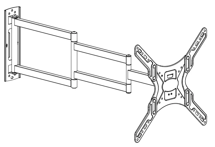
YD3018 Long Arm TV Mount
Instruction Manual
Contents
YD3018 Long Arm TV Mount
If you have any questions, please feel free to contact Customer Service via Amazon before returning.
Safety Caution
Please read this instruction carefully before installation. If you do not understand these instructions or have doubts about the safety of the installation, assembly or use of this product, please contact us.
- This product is designed for use in wood stud or solid concrete wall.
– DO NOT install into drywall alone. - The wall must be capable of supporting five times the weight of the TV and mount combined.
- Incorrect installation may result in product damage/property damage or body injury.
We shall bear no responsibility for any damage or injury resulted from incorrect installation, incorrect assembly or misuse.
WARNING: This product contains small items that could be a choking hazard if swallowed. Before starting assembly, verify all parts are included and undamaged. If any parts are missing or damaged, do not return the damaged item to your dealer; please contact our customer service team. Never use damaged parts!
Must Check Before Getting Started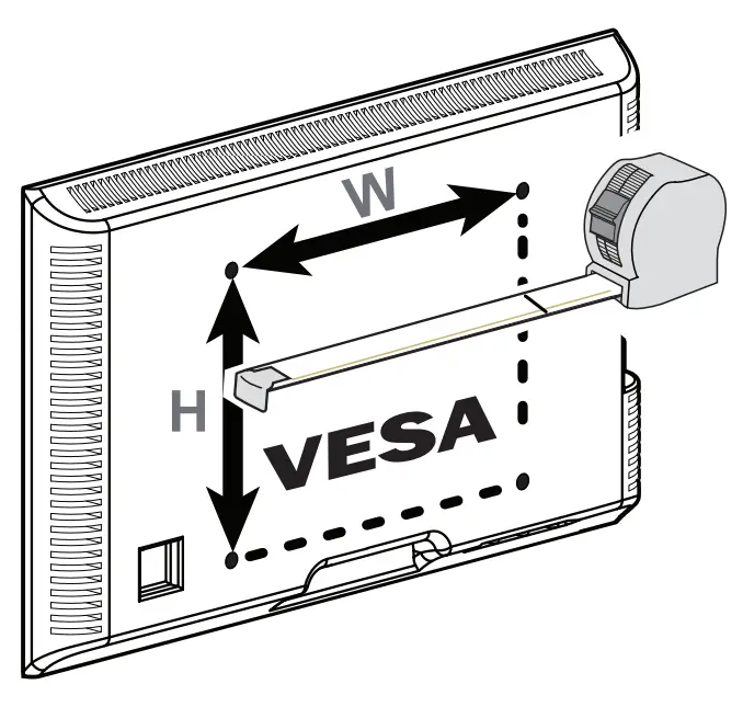
Minimum VESA Pattern (W × H): 100mm × 100mm / 4 in × 4 in
Maximum VESA Pattern (W × H): 400mm × 400mm / 16 in × 16 in![]()
WARNING
DO NOT exceed the maximum weight indicated.
This mounting system is intended for use only within the maximum weights indicated. Use with products heavier than the maximum weights indicated may result in failure of the mount and its accessories, causing possible damage or injury.
Verify Your Wall Construction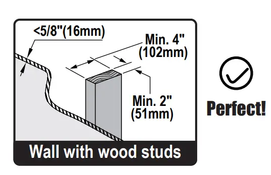 CAUTION:
Avoid potential personal injuries and property damage! Drywall covering the wall must not exceed 5/8 in. (16 mm). Minimum wood stud size: nominal 2 x 4 in. (51 x 102 mm) actual 1 ½ x 3 ½ in. (38 x 89 mm). CAUTION:
Avoid potential personal injuries and property damage! Mount the wall plate assembly directly onto the concrete surface (no surface covering).
CAUTION: DO NOT install into drywall alone.
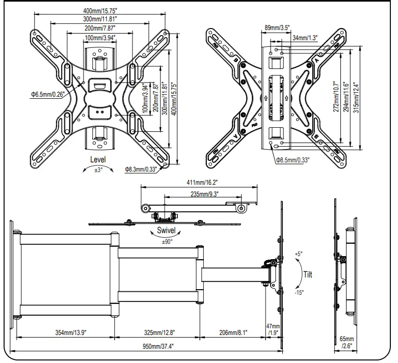
Product Dimensions
 Supplied Parts and Hardware
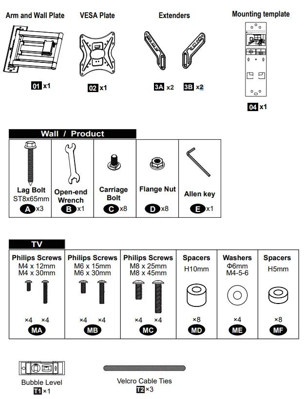 NOTE: Not all parts and hardware included will be used.
Extra Tools You Need (Not Supplied)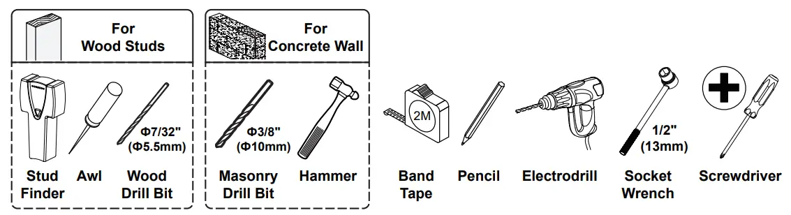
Attach Brackets to TV
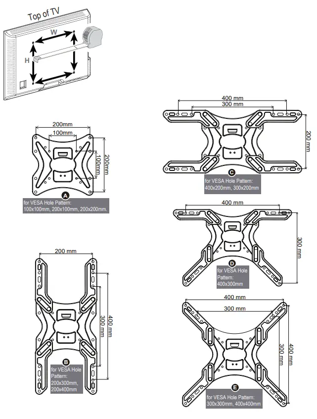
1-1 Select VESA Plate Configuration
Measure the width and the height of the square or rectangle formed from the VESA holes pattern. Select the configuration to use based on the measurement from TV.
| VESA Pattern (WxH) | Configuration | VESA Pattern (WxH) | Configuration |
| 100mm x 100mm | A | 300mm x 200mm | C |
| 200mm x 100mm | A | 400mm x 200mm | C |
| 200mm x 200mm | A | 400mm x 300mm | D |
| 200mm x 300mm | B | 300mm x 300mm | E |
| 200mm x 400mm | B | 400mm x 400mm | E |
 1-2 Assemble VESA Plate and Extenders (When VESA > 200mm)
If your TV hole pattern is greater than 200×200mm, attach extenders (3A,3B) to VESA plate (02) using Carriage Bolts (C) and Flange Nuts (D). 1-3 Select Correct TV Screw Diameter
 Select Correct TV Screw Length
 Which Situation Needs Spacers?
If the screw is too long or the surface is uneven, please choose the appropriate screws and spacers for your TV.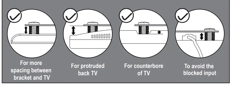
![]() Do not tighten the screws excessively or tighten them by using the Electro drill, or your TV might be damaged.
Do not tighten the screws excessively or tighten them by using the Electro drill, or your TV might be damaged. 2-A Attach Wall Plate to Wall
A-1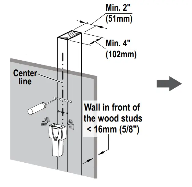 Locate your studs. Verify and mark the center of the stud by finding the stud edges using awl and stud finder.
 Line up the holes with your stud center line. Level the mounting template and mark the pilot hole locations.
A-2 Drill pilot holes using a Ф7/32 in (Ф5.5mm) diameter drill bit.
IMPORTANT:
Do not drill holes into where water pipes or electrical wires are located. Be sure to drill into the center of the stud.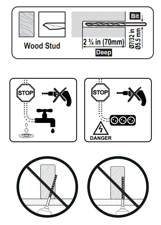 A-3
A-3

Install wall plate using lag bolts A with Socket Wrench,
NO Electrodrill. No anchors when installed onto the wood studs.
CAUTION:
To avoid potential personal injury or property damage:
All 2 lag bolts MUST BE firmly tightened to prevent unwanted movement of the wall plate assembly. Ensure the wall plate assembly is securely fastened to the wall before continuing on to the next step. To prevent the TV falling down, the
Arrow Must Keep UP at this step!!
2-B Attach Wall Plate to Wall
![]() OPTION B: Solid Concrete Wall Installation
OPTION B: Solid Concrete Wall Installation
B-1

Level the mounting template and mark the pilot hole locations.
B-2
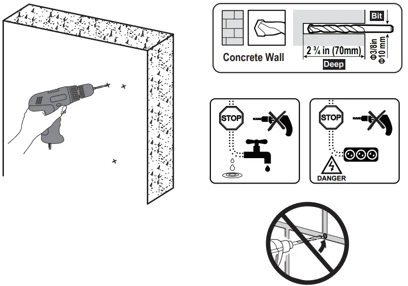
Drill pilot holes using a Ф3/8 in (Ф10mm) diameter drill bit.
IMPORTANT:
Do not drill holes into where water pipes or electrical wires are located, or mortar between blocks.
B-3

Use the hammer to knock anchors (not included) into the concrete wall. Be sure the anchors are seated flush with the concrete surface.
Install wall plate using lag bolts and anchors (not included) with Socket A Wrench, NO Electrodrill.
CAUTION:
To avoid potential personal injury or property damage:
All 3 lag bolts MUST BE firmly tightened to prevent unwanted movement of the wall plate assembly. Ensure the wall plate assembly is securely fastened to the wall before continuing on to the next step. To prevent the TV falling down, the Arrow Must Keep UP at this step!!
Hang and Secure TV to Wall Plate
3-1
Before hanging TV, please conduct “wall plate installation integrity test” first.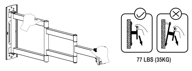
3-2
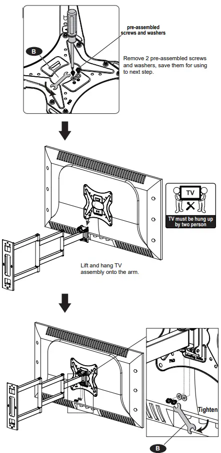
![]() Secure the TV plate to the arm and wall plate with the removed screws and washers from the previous step.
Secure the TV plate to the arm and wall plate with the removed screws and washers from the previous step.
Adjustments (If necessary)
Leveling Adjustment
If needed, TV can be leveled ±3 degrees via adjusting the 2 screws with the openend wrench(B).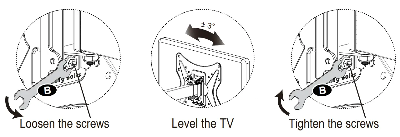
Tilt Adjustment
- Loosen the tilting bolts ×2.
- Adjust TV to your desired angle.
- Retighten the bolts to fix the intended angle.

Introduction to Applicable Scenarios
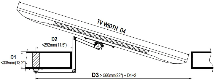
- The thickness of the wall D1 must be less than 292mm(11.5″).
- The distance from the center of the wood stud to the wall edge D2 must be less than 335mm(13.2″).
- The distance from the center of the wood stud to the wall edge D3 must be more than 560mm(22″) + TV width D4÷2. e.g. 65″ TV D3>1300mm(51.2″).

5-2 Wall corner installation
