Contents
 DEWALT DWANF DRILIT Self-Drilling Screws
Product Information
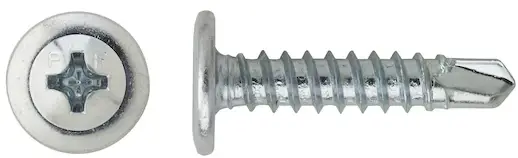
The product is a self-drilling screw with zinc plating and EPDM bonded sealing washers. It is available in multiple sizes and configurations for retention of 0.4 pcf and CA-B treated lumber with a maximum retention of 0.3 pcf. The fasteners are made of case hardened carbon steel and have a Stalgard zinc plating according to ASTM B633, SC1 Type III (Fe/Zn 5). They have a minimum plating requirement for Mild Service Condition and a Stalgard coating with a 1,000 hour rating in ASTM B117 salt spray test.
The product is code listed and has ICC-ES ESR-3294 approval for steel-to-steel applications and ICC-ES ESR-4367 approval for wood-to-steel applications.
Product Usage Instructions
- Select a torque adjustable screwgun that aligns with the recommended installation RPMs of the particular fastener. DEWALT VersaClutch Screwguns are recommended.
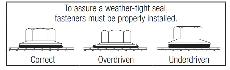
- Adjust the setting on the screwgun so that the tool does not overdrive the fastener.
- Attach an appropriate sized hex nut driver/phillips bit to the screwgun.
- Mount the screw fastener head into the driver.
- Place the screw fastener against the work surface in a perpendicular position.
- Begin driving the screw fastener into the base material.
- Drive the screw fastener until the head of the screw is in contact and snug tight with the work surface and/or the material being fastened.
GENERAL INFORMATION
- DRILIT®
- Self-Drilling Screws
PRODUCT DESCRIPTION
Drilit® self-drilling fasteners eliminate separate drilling and tapping operations for faster, more economical installations.
GENERAL APPLICATIONS AND USES
- Steel Framing
- Steel Decking
- Purlins and Girt
- HVAC and Ductwork
- Fastening Accessories to Steel Framing
- Fastening Plywood Subfloor to Steel Framing
FEATURES AND BENEFITS
- Eliminates separate drilling and tapping operations
- Fasteners coated with Stalgard® typically show no red rust or other base metal corrosion on significant surfaces after 1000 hours of salt spray exposure in accordance with ASTM B117
- Stalgard® coating provides improved corrosion resistance compared with fasteners with standard zinc plating
- Screws with EPDM Bonded Sealing washers are available in multiple sizes and configurations for applications requiring a weather-tight seal
- Fasteners coated with Stalgard® are compatible with ACQ-treated lumber with a maximum retention of 0.4 pcf and CA-B treated lumber with a maximum retention of 0.3 pcf
APPROVALS AND LISTINGS
- International Code Council, Evaluation Service (ICC-ES), ESR-3294
- International Code Council, Evaluation Service (ICC-ES), ESR-4367
- Code compliant with the International Building Code/International Residential
- Code: 2021 IBC/IRC, 2018 IBC/IRC, 2015 IBC/IRC, and 2012 IBC/IRC
- Tested in accordance with ICC-ES AC118 for use in Steel-to-Steel Connections
- Tested in accordance with ICC-ES AC500 for attaching Miscellaneous Building Materials to Steel
- City of Los Angeles, LABC & LARC Supplement (within ICC-ES evaluation reports)
- Florida Building Code Supplement including HVHZ (within ICC-ES evaluation reports)
GUIDE SPECIFICATIONS
05 05 23 – Metal Fastenings, 06 05 23 – Wood, Plastic and Composite Fastenings, 09 22 16.23 – Fasteners. Fasteners shall be Drilit self-drilling screws as supplied by DEWALT, Towson, MD. Fasteners shall be installed in accordance with published instructions and the Authority Having Jurisdiction.
MATERIAL SPECIFICATIONS
| Fastener Component | Specification | |
| Fastener | Case hardened carbon steel | |
|
Plating/Coating |
Zinc | Zinc plating according to ASTM B633, SC1 Type III (Fe/Zn 5). Minimum plating requirements for Mild Service Condition |
| Stalgard1 | Stalgard coating
1,000 hour rating in ASTM B117 salt spray test |
|
| 1. Stalgard is silver in color unless otherwise noted. | ||
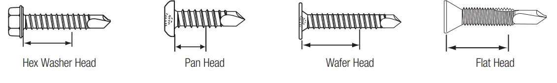
FASTENER MATERIALS
Carbon Steel
- Hex Washer Head
- Pan Head
- Wafer Head
- Flat Head
DIAMETERS
- #6, #8, #10, #12
- 1/4″, 5/16″
FINISH
- Stalgard®
- Zinc
DRILL POINT TYPES
- #1, #2, # 3, #4, #4.5, #5
FASTENER STYLES
- Standard Drill Screws
- Drill Screws with Extended Drilling Capacity
- Drill Screws with Bonded Sealing Washer
- Drill Screws for Wood-to-Metal Applications
CODE LISTED
ICC-ES ESR-3294 STEEL-TO-STEEL
STEEL-TO-STEEL ICC-ES ESR-4367 WOOD-TO-STEEL
INSTALLATION SPECIFICATIONS
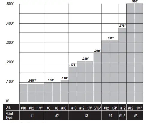
Point Size Selection
Maximum Combined Material Thickness By Point Type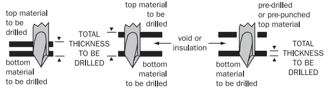
- Maximum Recommended Installation RPM
- Nominal Sheet Metal Sizes
- Nominal Screw Sizes
| Diameter | RPM | Gauge | Decimal (in.) | Thread Dia. | Decimal (in.) | |
| #6 | 2500 | |||||
| 26 | 0.018 | #6 | .138 | |||
| #8 | ||||||
| 24 | 0.024 | #8 | .164 | |||
| #10 | ||||||
| 22 | 0.030 | #10 | .190 | |||
| #12 | ||||||
| 20 | 0.036 | #12 | .216 | |||
| #12** | 1800 | |||||
| 18 | 0.048 | 1/4″ | .250 | |||
| 1/4″ | ||||||
| 16 | 0.060 | 5/16″ | .3125 | |||
| 5/16″ | 1200 | |||||
| 14 | 0.075 | |||||
| ** Applies to #12 diameter screws with point types 4,
4.5 and 5 |
||||||
| 12 | 0.105 | |||||
Drilling and Tapping Capacity (Maximum Material Thickness)*
Lapped panels: 18 ga. to 18 ga.
* NOTE: Some drill and tap capacities may vary due to special features on some fasteners. Refer to ordering and technical information for difference in drilling and tapping capacities for any individual fastener
INSTALLATION PROCEDURES
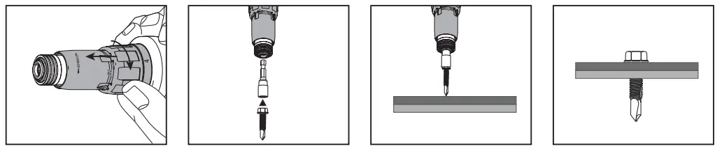
- Select a torque adjustable screwgun that aligns with the recommended installation RPM’s of the particular fastener
- (DEWALT Versa Clutch Screwguns are recommended). Adjust the setting on the screwgun so that the tool does not overdrive the fastener.
- Attach an appropriate sized hex nut driver/ Philips bit to the screwgun. Mount the screw fastener head into the driver.
- Place the screw fastener against the work surface. While the screw fastener is in a perpendicular position, begin driving the screw fastener into the base material.
- Note: The ideal speed and pressure will depend on the characteristics of the base material as well as the screw size and point type. A trial installation is suggested to determine the optimal tool setting, speed and pressure for the material and application.
- Drive the screw fastener until the head of the screw is in contact and snug tight with the work surface and/or the material being fastened.
Minimum Screw Spacing and Edge Distance1,2
| Screw Diameter: d (in.) | Fastened Material (in.) | Minimum Spacing: 3d (in.) | Minimum Edge Distance: 1.5d (in.) | Minimum Edge Distance For Framing Members Under The 2018, 2015,
and 2012 IBC: 3d (in.) |
| 0.138
(#6) |
Steel | 7/16 | 7/32 | 7/16 |
| 0.164
(#8) |
Steel | 1/2 | 1/4 | 1/2 |
| 0.190
(#10) |
Steel | 9/16 | 5/16 | 9/16 |
| 0.216
(#12) |
Steel | 11/16 | 3/8 | 11/16 |
| 0.250 (1/4″) | Steel | 3/4 | 3/8 | 3/4 |
| 0.3125 (5/16″) | Steel | 15/16 | 1/2 | 15/16 |
|
||||
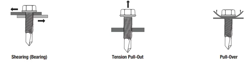
Fastener Strengths1,2,3,4,5,6,7
|
Description |
Tension (lbf) | Shear (lbf) | Minimum Torsional Strength
(In-lbs) |
||||
| Ultimate | ASD | LRFD | Ultimate | ASD | LRFD | ||
| #6-20 | 1,345 | 450 | 675 | 815 | 270 | 410 | 24 |
| #8-18 | 1,615 | 535 | 805 | 1,100 | 365 | 550 | 42 |
| #10-16 | 2,670 | 890 | 1,335 | 1,675 | 555 | 835 | 61 |
| #10-24 | 2,635 | 875 | 1,315 | 1,570 | 520 | 785 | 65 |
| #12-14 | 3,210 | 1,070 | 1,605 | 1,785 | 595 | 890 | 92 |
| #12-24 | 3,550 | 1,180 | 1,775 | 2,185 | 725 | 1,090 | 100 |
| 1/4″-14 | 5,020 | 1,670 | 2,510 | 2,305 | 765 | 1,150 | 150 |
| 1/4″-20 | 5,190 | 1,730 | 2,595 | 2,980 | 990 | 1,490 | 168 |
| 5/16″-18 | 8,710 | 2,900 | 4,355 | 4,720 | 1,570 | 2,360 | 438 |
|
|||||||
Ultimate Shear (Bearing) Capacity of Screw Connections, lbf1,3
| Description | Point Type | Steel Thickness (Lapped Sheets/Bars) | ||||||||
| 26-26 Ga. | 24-24 Ga. | 22-22 Ga. | 20-20 Ga. | 18-18 Ga. | 16-16 Ga. | 14-14 Ga. | 12-12 Ga. | 1/8″-1/8″ | ||
| #6-20 | #2 | 170 [2] | 260 [2] | 365 [2] | 480 [2] | 740[ 2] | – | – | – | – |
| #8-18 | #2 | 300 | 500 | 540 | 740 | 1,045 | – | – | – | – |
| #10-16 | #1 | 400 | 585 | 670 | 880 | 1,330 | – | – | – | – |
| #10-16 | #3 | 200 [2] | 460 | 520 | 730 | 1,250 | 1,520 | 1,670 | – | – |
| #10-24 | #2 | 200 [2] | 305 [2] | 430 [2] | 565 [2] | 865 [2] | – | – | – | – |
| #12-14 | #1 | 435 | 715 | 760 | 1,030 | 1,545 | – | – | – | – |
| #12-14 | #3 | 210 [2] | 325 [2] | 455 [2] | 775 | 1,360 | 1,620 | 1,970 | 1,990 | – |
| #12-24 | #4 | – | – | – | – | – | 1,430 | 1,930 | 2,455 | 2,570 |
| #12-24 | #4.5 | – | – | – | – | – | 1,385 | 1,920 | 2,170 | 2,255 |
| #12-24 | #5 | – | – | – | – | – | 1,350 | 1,825 | 2,150 | 2,225 |
| 1/4″-14 | #1 | 515 | 860 | 890 | 1,300 | 1,770 | – | – | – | – |
| 1/4″-14 | #3 | 225 [2] | 350 [2] | 490 [2] | 930 | 1,445 | 2,100 | 2,580 | 2,650 | – |
| 1/4″-20 | #5 | – | – | – | – | – | 1,655 | 2,275 | – | 3,210 |
|
||||||||||
Allowable (ASD) and Design (LRFD) Shear (Bearing) Capacity of Screw Connections, lbf1,2,3,4
| Description | Point Type | Material Thickness | |||||||||||||||||
| 26-26 Ga. | 24-24 Ga. | 22-22 Ga. | 20-20 Ga. | 18-18 Ga. | 16-16 Ga. | 14-14 Ga. | 12-12 Ga. | 1/8″-1/8″ | |||||||||||
| ASD | LRFD | ASD | LRFD | ASD | LRFD | ASD | LRFD | ASD | LRFD | ASD | LRFD | ASD | LRFD | ASD | LRFD | ASD | LRFD | ||
| #6-20 | #2 | 55 | 80 | 85 | 130 | 120 | 180 | 155 | 235 | 245 | 365 | – | – | – | – | – | – | – | – |
| #8-18 | #2 | 100 | 150 | 165 | 250 | 180 | 270 | 245 | 370 | 345 | 520 | – | – | – | – | – | – | – | – |
| #10-16 | #1 | 130 | 200 | 195 | 290 | 220 | 335 | 290 | 440 | 440 | 665 | – | – | – | – | – | – | – | – |
| #10-16 | #3 | 65 | 100 | 150 | 230 | 170 | 260 | 240 | 365 | 415 | 625 | 505 | 760 | 555 | 835 | – | – | – | – |
| #10-24 | #2 | 65 | 100 | 100 | 155 | 145 | 215 | 190 | 285 | 290 | 435 | 405 | 605 | – | – | – | – | – | – |
| #12-14 | #1 | 145 | 215 | 235 | 355 | 250 | 380 | 340 | 515 | 515 | 770 | – | – | – | – | – | – | – | – |
| #12-14 | #3 | 70 | 105 | 105 | 165 | 150 | 230 | 255 | 385 | 450 | 680 | 540 | 810 | 655 | 985 | 660 | 995 | – | – |
| #12-24 | #4 | – | – | – | – | – | – | – | – | – | – | 475 | 715 | 640 | 965 | 815 | 1,225 | 855 | 1,285 |
| #12-24 | #4.5 | – | – | – | – | – | – | – | – | – | – | 460 | 690 | 640 | 960 | 720 | 1,085 | 750 | 1,125 |
| #12-24 | #5 | – | – | – | – | – | – | – | – | – | – | 450 | 675 | 605 | 910 | 715 | 1,075 | 740 | 1,110 |
| 1/4″-14 | #1 | 170 | 255 | 285 | 430 | 295 | 445 | 430 | 650 | 590 | 885 | – | – | – | – | – | – | – | – |
| 1/4″-14 | #3 | 75 | 110 | 115 | 175 | 160 | 245 | 310 | 465 | 480 | 720 | 700 | 1,050 | 860 | 1,290 | 880 | 1,325 | – | – |
| 1/4″-20 | #5 | – | – | – | – | – | – | – | – | – | – | 550 | 825 | 755 | 1,135 | – | – | 1,070 | 1,605 |
|
|||||||||||||||||||
Ultimate Tension Pull-Out Capacity of Screw Connections, lbf1,3
| Description | Point Type | Thickness of Steel Not in Contact with Screw Head | |||||||||||||
| 26 Ga. | 24 Ga. | 22 Ga. | 20 Ga. | 18 Ga. | 16 Ga. | 14 Ga. | 12 Ga. | 0.12 | 1/8″ | 3/16″ | 1/4″ | 5/16″ | 3/8″ | ||
| #6-20 | #2 | 95 [2] | 125 [2] | 155 [2] | 190 [2] | 250 [2] | 315 [2] | 395 [2] | – | – | – | – | – | – | – |
| #8-18 | #2 | 120 | 195 | 265 | 300 | 490 | 700 | 960 | – | – | – | – | – | – | – |
| #10-16 | #1 | 150 | 240 | 315 | 360 | 565 | 825 | 1,090 | – | – | – | – | – | – | – |
| #10-16 | #2 | 130 | 205 | 270 | 300 | 420 | 550 | 660 | 1,125 | – | – | – | – | – | – |
| #10-16 | #3 | 130 | 205 | 270 | 300 | 420 | 550 | 660 | 1,125 | – | – | – | – | – | – |
| #10-24 | #2 | 130 [2] | 175 [2] | 220 [2] | 260 [2] | 345 [2] | 435 [2] | 545 [2] | 760 [2] | – | – | – | – | – | – |
| #10-24 | #3 | 130 [2] | 175 [2] | 220 [2] | 260 [2] | 345 [2] | 435 [2] | 545 [2] | 760 [2] | – | – | – | – | – | – |
| #10-24 | #3 w/wings | – | – | – | – | – | 535 | – | – | – | 1,500 | – | – | – | – |
| #12-14 | #1 | 160 | 260 | 330 | 390 | 640 | 920 | 1,260 | – | – | – | – | – | – | – |
| #12-14 | #3 | 140 | 210 | 295 | 345 | 580 | 765 | 1,075 | 1,550 | 1,955 | – | – | – | – | – |
| #12-24 | #4 w/wings | – | – | – | – | 585 | – | – | – | – | 1,605 | – | 2,085 | – | – |
| #12-24 | #4 | – | – | – | 310 | 450 | 495 [2] | 620 [2] | 865 [2] | 990 [2] | 1,415 | 3,235 | 3,770 | – | – |
| #12-24 | #4.5 | – | – | – | 310 | 450 | 495 [2] | 620 [2] | 865 [2] | 990 [2] | 1,415 | 3,235 | 3,770 | – | 4,125 |
| #12-24 | #5 | – | – | – | 310 | 450 | 495 [2] | 620 [2] | 865 [2] | 990 [2] | 1,415 | 3,235 | 3,770 | – | 4,125 |
| 1/4″-14 | #1 | 225 | 340 | 430 | 570 | 800 | 1,165 | – | – | – | – | – | – | – | – |
| 1/4″-14 | #3 | 150 | 235 | 300 | 340 | 700 | 890 | 1,160 | 1,795 | 2,120 | – | – | – | – | – |
| 1/4″-20 | #4 w/wings | – | – | – | – | – | 535 | – | – | – | 1,670 | – | 4,065 | 4,170 | – |
| 1/4″-20 | #5 | – | – | – | 345 [2] | 460 [2] | 575 [2] | 720 [2] | 1,005 [2] | 1,150 [2] | 1,550 | – | 4,825 | 5,285 | 5,400 |
| 5/16″-18 | #3 | – | – | – | 455 | 565 | 1,205 | 1,710 | 2,420 | 2,600 | – | 3,715 | 5,120 | – | – |
|
|||||||||||||||
Allowable Tension Pull-Out Capacity of Screw Connections, lbf1,2
| Description | Point Type | Thickness of Steel Not in Contact with Screw Head | |||||||||||||
| 26 Ga. | 24 Ga. | 22 Ga. | 20 Ga. | 18 Ga. | 16 Ga. | 14 Ga. | 12 Ga. | 0.12 | 1/8″ | 3/16″ | 1/4″ | 5/16″ | 3/8″ | ||
| #6-20 | #2 | 30 | 40 | 50 | 60 | 80 | 105 | 115 | – | – | – | – | – | – | – |
| #8-18 | #2 | 40 | 65 | 85 | 100 | 160 | 230 | 320 | – | – | – | – | – | – | – |
| #10-16 | #1 | 50 | 80 | 105 | 120 | 185 | 275 | 360 | – | – | – | – | – | – | – |
| #10-16 | #2 | 40 | 65 | 90 | 100 | 140 | 180 | 220 | 375 | – | – | – | – | – | – |
| #10-16 | #3 | 40 | 65 | 90 | 100 | 140 | 180 | 220 | 375 | – | – | – | – | – | – |
| #10-24 | #2 | 40 | 55 | 70 | 85 | 115 | 145 | 180 | 250 | – | – | – | – | – | – |
| #10-24 | #3 | 40 | 55 | 70 | 85 | 115 | 145 | 180 | 250 | – | – | – | – | – | – |
| #10-24 | #3 w/wings | – | – | – | – | – | 175 | – | – | – | 500 | – | – | – | – |
| #12-14 | #1 | 50 | 85 | 110 | 130 | 210 | 305 | 420 | – | – | – | – | – | – | – |
| #12-14 | #3 | 45 | 70 | 95 | 115 | 190 | 255 | 355 | 515 | 650 | – | – | – | – | – |
| #12-24 | #4 w/wings | – | – | – | – | – | 195 | – | – | – | 535 | – | 695 | – | – |
| #12-24 | #4 | – | – | – | 100 | 150 | 165 | 205 | 290 | 330 | 470 | 1,075 | 1,255 | – | – |
| #12-24 | #4.5 | – | – | – | 100 | 150 | 165 | 205 | 290 | 330 | 470 | 1,075 | 1,255 | – | 1,375 |
| #12-24 | #5 | – | – | – | 100 | 150 | 165 | 205 | 290 | 330 | 470 | 1,075 | 1,255 | – | 1,375 |
| 1/4″-14 | #1 | 75 | 110 | 140 | 190 | 265 | 385 | – | – | – | – | – | – | – | – |
| 1/4″-14 | #3 | 50 | 75 | 100 | 110 | 230 | 295 | 385 | 595 | 705 | – | – | – | – | – |
| 1/4″-20 | #4 w/wings | – | – | – | – | – | 175 | – | – | – | 555 | – | 1,355 | 1,390 | – |
| 1/4″-20 | #5 | – | – | – | 115 | 155 | 190 | 240 | 335 | 385 | 515 | – | 1,605 | – | 1,800 |
| 5/16″-18 | #3 | – | – | – | 150 | 185 | 400 | 570 | 805 | 865 | – | 1,235 | 1,705 | – | – |
|
|||||||||||||||
 Design (LRFD) Tension Pull-Out Capacity Of Screw Connections, lbf1,2
| Description | Point Type | Thickness of Steel Not in Contact with Screw Head | |||||||||||||
| 26 Ga. | 24 Ga. | 22 Ga. | 20 Ga. | 18 Ga. | 16 Ga. | 14 Ga. | 12 Ga. | 0.12 | 1/8″ | 3/16″ | 1/4″ | 5/16″ | 3/8″ | ||
| #6-20 | #2 | 45 | 60 | 75 | 95 | 125 | 155 | 175 | – | – | – | – | – | – | – |
| #8-18 | #2 | 60 | 95 | 130 | 150 | 245 | 350 | 480 | – | – | – | – | – | – | – |
| #10-16 | #1 | 75 | 120 | 155 | 180 | 280 | 410 | 545 | – | – | – | – | – | – | – |
| #10-16 | #2 | 65 | 100 | 135 | 150 | 210 | 275 | 330 | 565 | – | – | – | – | – | – |
| #10-16 | #3 | 65 | 100 | 135 | 150 | 210 | 275 | 330 | 565 | – | – | – | – | – | – |
| #10-24 | #2 | 65 | 85 | 105 | 130 | 170 | 215 | 270 | 380 | – | – | – | – | – | – |
| #10-24 | #3 | 65 | 85 | 105 | 130 | 170 | 215 | 270 | 380 | – | – | – | – | – | – |
| #10-24 | #3 w/wings | – | – | – | – | – | 265 | – | – | – | 750 | – | – | – | – |
| #12-14 | #1 | 80 | 130 | 165 | 195 | 320 | 460 | 630 | – | – | – | – | – | – | – |
| #12-14 | #3 | 70 | 105 | 145 | 170 | 290 | 380 | 535 | 775 | 975 | – | – | – | – | – |
| #12-24 | #4 w/wings | – | – | – | – | – | 290 | – | – | – | 800 | – | 1,040 | – | – |
| #12-24 | #4 | – | – | – | 155 | 225 | 250 | 310 | 435 | 495 | 705 | 1,615 | 1,885 | – | – |
| #12-24 | #4.5 | – | – | – | 155 | 225 | 250 | 310 | 435 | 495 | 705 | 1,615 | 1,885 | – | 2,060 |
| #12-24 | #5 | – | – | – | 155 | 225 | 250 | 310 | 435 | 495 | 705 | 1,615 | 1,885 | – | 2,060 |
| 1/4″-14 | #1 | 110 | 170 | 215 | 285 | 400 | 580 | – | – | – | – | ��� | – | – | – |
| 1/4″-14 | #3 | 75 | 115 | 150 | 170 | 350 | 445 | 580 | 895 | 1,060 | – | – | – | – | – |
| 1/4″-20 | #4 w/wings | – | – | – | – | – | 265 | – | – | – | 835 | – | 2,030 | 2,085 | – |
| 1/4″-20 | #5 | – | – | – | 170 | 230 | 285 | 360 | 500 | 575 | 775 | – | 2,410 | – | 2,700 |
| 5/16″-18 | #3 | – | – | – | 225 | 280 | 600 | 855 | 1,210 | 1,300 | – | 1,855 | 2,560 | – | – |
|
|||||||||||||||
Ultimate, Allowable (ASD) And Design (LRFD) Pull-Over Capacity for Light Gauge Steel Framing with Screws1,2,3,4
| Fastener Description | Minimum Thickness of Steel or Framing Member in Contact with Screw Head | ||||||||||||||||
| 25 Gauge | 22 Gauge | 20 Gauge | 18 Gauge | 16 Gauge | |||||||||||||
| Ult. | ASD | LRFD | Ult. | ASD | LRFD | Ult. | ASD | LRFD | Ult. | ASD | LRFD | Ult. | ASD | LRFD | |||
| Drilit® | #6-20 | 1/4″ Hex washer Head | 445 | 150 | 225 | 635 | 210 | 320 | 765 | 255 | 385 | 1,015 | 340 | 510 | 1,270 | 425 | 635 |
| Drilit�� | #8-18 | 1/4″ Hex washer Head | 475 | 160 | 240 | 675 | 225 | 340 | 810 | 270 | 405 | 1,080 | 360 | 540 | 1,350 | 450 | 675 |
| Drilit® | #10-16 | 5/16″ Hex washer Head | 565 | 190 | 285 | 805 | 270 | 405 | 965 | 320 | 485 | 1,285 | 430 | 645 | 1,610 | 535 | 805 |
| Drilit® | #12-24 | 5/16″ Hex washer Head | 585 | 195 | 295 | 840 | 280 | 420 | 1,005 | 335 | 505 | 1,340 | 445 | 670 | 1,675 | 560 | 840 |
| Drilit® | 1/4″-14 | 5/16″ Hex washer Head | 585 | 195 | 295 | 840 | 280 | 420 | 1,005 | 335 | 505 | 1,340 | 445 | 670 | 1,675 | 560 | 840 |
| Drilit® | 1/4″-14 | 3/8″ Hex washer Head | 705 | 235 | 355 | 1,010 | 335 | 505 | 1,210 | 405 | 605 | 1,615 | 540 | 810 | 2,020 | 675 | 1,010 |
|
Drilit® |
1/4″-14 |
3/8″ Hex Oversized washer Head |
950 |
315 |
475 |
1,360 |
455 |
680 |
1,635 |
545 |
820 |
2,180 |
725 |
1,090 |
2,725 |
910 |
1,365 |
| Drilit® | 1/4″-20 | 3/8″ Hex washer Head | 840 | 280 | 420 | 1,200 | 400 | 600 | 1,440 | 480 | 720 | 1,920 | 640 | 960 | 2,400 | 800 | 1,200 |
| Drilit® | 5/16″-18 | 3/8″ Hex washer Head | 840 | 280 | 420 | 1,200 | 400 | 600 | 1,440 | 480 | 720 | 1,920 | 640 | 960 | 2,400 | 800 | 1,200 |
| Drilit® with Bonded Sealing washer | #8-18 | 1/4″ Hex washer Head | 605 | 200 | 305 | 675 | 225 | 340 | 810 | 270 | 405 | 1,080 | 360 | 540 | 1,350 | 450 | 675 |
| Drilit® with Bonded Sealing washer | #10-16 | 5/16″ Hex washer Head | 695 | 230 | 350 | 805 | 270 | 405 | 965 | 320 | 485 | 1,285 | 430 | 645 | 1,610 | 535 | 805 |
| Drilit® with Bonded Sealing washer | #12-24 | 5/16″ Hex washer Head | 715 | 240 | 360 | 840 | 280 | 420 | 1,005 | 335 | 505 | 1,340 | 445 | 670 | 1,675 | 560 | 840 |
| Drilit® with Bonded Sealing washer | 1/4″-14 | 5/16″ Hex washer Head | 715 | 240 | 360 | 840 | 280 | 420 | 1,005 | 335 | 505 | 1,340 | 445 | 670 | 1,675 | 560 | 840 |
| Drilit® with Bonded Sealing washer | 1/4″-14 | 3/8″ Hex washer Head | 705 | 235 | 355 | 1,010 | 335 | 505 | 1,210 | 405 | 605 | 1,615 | 540 | 810 | 2,020 | 675 | 1,010 |
| Drilit® Flo-Seal® | #12-14 | 5/16″ Flo-Seal | 630 | 210 | 315 | 715 | 240 | 360 | 860 | 285 | 430 | 1,145 | 380 | 575 | 1,435 | 480 | 720 |
|
|||||||||||||||||
ORDERING INFORMATION
Drilit® Standard Drill Screws
|
Cat. No. |
Description (Diameter – TPI x Nominal Length) |
Point Type |
Finish |
Maximum Load Bearing Length1
(in.) |
Minimum Protrusion Length2 | Nominal Head Diameter3 (in.) | Nominal Head Height4 (in.) |
Qty / Carton |
Qty / Case |
| #6 DIAMETER, 1/4″ HEX WASHER HEAD | |||||||||
| DFSEDA160-100 | #6 – 20 x 3/4″ | #2 | ZINC | 0.406 | 11/32″ | 0.315 | 0.110 | 100 | 1000 |
| DFSEDA190-100 | #6 – 20 x 1″ | #2 | ZINC | 0.656 | 11/32″ | 0.315 | 0.110 | 100 | 1000 |
| #8 DIAMETER, 1/4″ HEX WASHER HEAD | |||||||||
| DFSEDA236 | #8 – 18 x 1/2″ | #2 | STALGArD® | 0.125 | 3/8″ | 0.335 | 0.130 | 10000 | – |
| DFSEDA250-100 | #8 – 18 x 5/8″ | #2 | ZINC | 0.250 | 3/8″ | 0.335 | 0.130 | 100 | 1000 |
| DFSEDA260-100 | #8 – 18 x 3/4″ | #2 | ZINC | 0.375 | 3/8″ | 0.335 | 0.130 | 100 | 1000 |
| DFSEDA261 | #8 – 18 x 3/4″ | #2 | STALGArD® | 0.375 | 3/8″ | 0.335 | 0.130 | 8000 | – |
| DFSEDA285-100 | #8 – 18 x 1″ | #2 | ZINC | 0.625 | 3/8″ | 0.335 | 0.130 | 100 | 1000 |
| DFSEDA286 | #8 – 18 x 1″ | #2 | STALGArD® | 0.625 | 3/8″ | 0.335 | 0.130 | 5000 | – |
| DFSEDA290-100 | #8 – 18 x 1-1/4″ | #2 | ZINC | 0.875 | 3/8″ | 0.335 | 0.130 | 100 | 1000 |
| DFSEDA295-100 | #8 – 18 x 1-1/2″ | #2 | ZINC | 1.125 | 3/8″ | 0.335 | 0.130 | 100 | 1000 |
| #8 DIAMETER, #2 PHILLIPS PAN HEAD | |||||||||
| DFSEDD266 | #8 – 18 x 3/4″ | #2 | STALGArD® | 0.375 | 3/8″ | 0.315 | 0.110 | 10000 | – |
| #10 DIAMETER, 5/16″ HEX WASHER HEAD | |||||||||
| DFSEDB401 | #10 – 16 x 1/2″ | #2 | STALGArD® | 0.094 | 13/32″ | 0.400 | 0.185 | 5000 | – |
| DFSEDB426 | #10 – 16 x 5/8″ | #3 | STALGArD® | 0.125 | 1/2″ | 0.400 | 0.185 | 6000 | – |
| DFSEDC450 | #10 – 16 x 3/4″ | #1 | STALGArD® | 0.188 | 9/16″ | 0.400 | 0.185 | 5000 | – |
| DFSEDB445-100 | #10 – 16 x 3/4″ | #3 | ZINC | 0.250 | 1/2″ | 0.400 | 0.185 | 100 | 1000 |
| DFSEDB446 | #10 – 16 X 3/4″ | #3 | STALGArD® | 0.250 | 1/2″ | 0.400 | 0.185 | 6000 | – |
| DFSEDB485-100 | #10 – 16 x 1″ | #3 | ZINC | 0.500 | 1/2″ | 0.400 | 0.185 | 100 | 1000 |
| DFSEDB486 | #10 – 16 x 1″ | #3 | STALGArD® | 0.500 | 1/2″ | 0.400 | 0.185 | 5000 | – |
| DFSEDB540-100 | #10 – 16 x 1-1/2″ | #3 | ZINC | 1.000 | 1/2″ | 0.400 | 0.170 | 100 | 1000 |
| DFSEDB541 | #10 – 16 x 1-1/2″ | #3 | STALGArD® | 1.000 | 1/2″ | 0.400 | 0.185 | 3000 | – |
| DFSEDB571 | #10 – 16 x 2″ | #3 | STALGArD® | 1.500 | 1/2″ | 0.400 | 0.185 | 2000 | – |
| #10 DIAMETER, 5/16″ HEX WASHER HEAD WITH SERRATIONS | |||||||||
| DFSEFC460 | #10 – 16 x 3/4″ | #3 | ZINC | 0.250 | 1/2″ | 0.400 | 0.215 | 6000 | – |
| #12 DIAMETER, 5/16″ HEX WASHER HEAD | |||||||||
| DFSEDC745 | #12 – 14 x 3/4″ | #1 | STALGArD® | 0.188 | 9/16″ | 0.415 | 0.180 | 5000 | – |
| DFSEDB740-100 | #12 – 14 x 3/4″ | #3 | ZINC | 0.188 | 9/16″ | 0.415 | 0.180 | 100 | 1000 |
| DFSEDB741 | #12 – 14 x 3/4″ | #3 | STALGArD® | 0.188 | 9/16″ | 0.415 | 0.180 | 5000 | – |
| DFSEDB760-100 | #12 – 14 x 1″ | #3 | ZINC | 0.438 | 9/16″ | 0.415 | 0.180 | 100 | 1000 |
| DFSEDB761 | #12 – 14 x 1″ | #3 | STALGArD® | 0.438 | 9/16″ | 0.415 | 0.180 | 4000 | – |
| DFSEDB782 | #12 – 14 x 1-1/4″ | #3 | STALGArD® | 0.688 | 9/16″ | 0.415 | 0.180 | 3000 | – |
| DFSEDB800-050 | #12 – 14 x 1-1/2″ | #3 | ZINC | 0.938 | 9/16″ | 0.415 | 0.180 | 50 | 500 |
| DFSEDB801 | #12 – 14 x 1-1/2″ | #3 | STALGArD® | 1.438 | 9/16″ | 0.415 | 0.180 | 2500 | – |
| DFSEDB820-050 | #12 – 14 x 2″ | #3 | ZINC | 1.438 | 9/16″ | 0.415 | 0.180 | 50 | 500 |
| DFSEDB821 | #12 – 14 x 2″ | #3 | STALGArD® | 1.438 | 9/16″ | 0.415 | 0.180 | 2000 | – |
| DFSEDB830 | #12 – 14 x 2-1/2″ | #3 | STALGArD® | 1.938 | 9/16″ | 0.415 | 0.180 | 1500 | – |
| DFSEDB840 | #12 – 14 x 3″ | #3 | STALGArD® | 2.438 | 9/16″ | 0.415 | 0.180 | 1000 | – |
| DFSEDB845 | #12 – 14 x 4″ | #3 | STALGArD® | 3.438 | 9/16″ | 0.415 | 0.180 | 500 | – |
|
|||||||||
Drilit® Standard Drill Screws, Continued
| Cat. No. | Description (Diameter – TPI x Nominal Length) | Point Type | Finish | Maximum Load Bearing Length1
(in.) |
Minimum Protrusion Length2 | Nominal Head Diameter3 (in.) | Nominal Head Height4 (in.) | Qty / Carton | Qty / Case |
| 1/4″ DIAMETER, 5/16″ HEX WASHER HEAD | |||||||||
| DFSEDC930 | 1/4″ – 14 x 7/8 | #1 | STALGArD® | 0.313 | 9/16″ | 0.415 | 0.180 | 4000 | – |
| 1/4″ DIAMETER, 3/8″ HEX WASHER HEAD | |||||||||
| DFSEDB935-100 | 1/4″ -14 x 3/4″ | #3 | ZINC | 0.125 | 5/8″ | 0.500 | 0.230 | 100 | 1000 |
| DFSEDB936 | 1/4″ – 14 x 3/4″ | #3 | STALGArD® | 0.125 | 5/8″ | 0.500 | 0.230 | 3500 | – |
| DFSEDB945 | 1/4″ -14 x 1″ | #3 | ZINC | 0.375 | 5/8″ | 0.500 | 0.230 | 3000 | – |
| DFSEDB946 | 1/4″ – 14 x 1″ | #3 | STALGArD® | 0.375 | 5/8″ | 0.500 | 0.230 | 3000 | – |
| DFSEDB955-050 | 1/4″ – 14 x 1-1/4″ | #3 | ZINC | 0.625 | 5/8″ | 0.500 | 0.230 | 50 | 500 |
| DFSEDB956 | 1/4″ – 14 x 1-1/4″ | #3 | STALGArD® | 0.625 | 5/8″ | 0.500 | 0.230 | 2000 | – |
| DFSEDB960-050 | 1/4″ – 14 x 1-1/2″ | #3 | ZINC | 0.875 | 5/8″ | 0.500 | 0.230 | 50 | 500 |
| DFSEDB961 | 1/4″ – 14 x 1-1/2″ | #3 | STALGArD® | 0.875 | 5/8″ | 0.500 | 0.230 | 2000 | – |
| DFSEDB970-050 | 1/4″ – 14 x 2″ | #3 | ZINC | 1.375 | 5/8″ | 0.500 | 0.230 | 50 | 500 |
| DFSEDB971 | 1/4″ – 14 x 2″ | #3 | STALGArD® | 1.375 | 5/8″ | 0.500 | 0.230 | 1500 | – |
| DFSEDB975-025 | 1/4″ – 14 x 2-1/2″ | #3 | ZINC | 1.875 | 5/8″ | 0.500 | 0.230 | 25 | 250 |
| DFSEDB976 | 1/4″ – 14 x 2-1/2″ | #3 | STALGArD® | 1.875 | 5/8″ | 0.500 | 0.230 | 1000 | – |
| DFSEDB981 | 1/4″ – 14 x 3��� | #3 | STALGArD® | 2.375 | 5/8″ | 0.500 | 0.230 | 800 | – |
| DFSEDB983 | 1/4″ – 14 x 4″ | #3 | STALGArD® | 3.375 | 5/8″ | 0.500 | 0.230 | 500 | – |
| 1/4″ DIAMETER, 3/8″ HEX OVERSIZED (11/16″) WASHER HEAD | |||||||||
| DFSEDB947 | 1/4″ -14 x 1″ | #3 | ZINC | 0.375 | 5/8″ | 0.675 | 0.230 | 2000 | – |
| 5/16″ DIAMETER, 3/8″ HEX WASHER HEAD | |||||||||
| DFSEDB990-010 | 5/16″ – 18 x 1″ | #3 | ZINC | 0.250 | 3/4″ | 0.600 | 0.270 | 10 | 100 |
| DFSEDB991 | 5/16″ – 18 x 1″ | #3 | STALGArD® | 0.250 | 3/4″ | 0.600 | 0.270 | 1000 | – |
| DFSEDB994 | 5/16″ – 18 x 1-1/4″ | #3 | STALGArD® | 0.500 | 3/4″ | 0.600 | 0.270 | 1000 | – |
| DFSEDB998 | 5/16″ – 18 x 1-1/2″ | #3 | STALGArD® | 0.750 | 3/4″ | 0.600 | 0.270 | 1000 | – |
|
|||||||||
Drilit® Drill Screws with Extended Drilling Capacity
| Cat. No. | Description (Diameter – TPI x Nominal Length) | Point Type | Finish | Maximum Load Bearing Length1
(in.) |
Minimum Protrusion Length2 | Nominal Head Diameter3 (in.) | Nominal Head Height4 (in.) | Qty / Carton | Qty / Case |
| #12 DIAMETER, 5/16″ HEX WASHER HEAD | |||||||||
| DFSEDC801 | #12 – 24 x 7/8″ | #4 | STALGArD® | 0.250 | 5/8″ | 0.415 | 0.185 | 4500 | – |
| DFSEDC816 | #12 – 24 x 1-1/4″ | #4.5 | STALGArD® | 0.500 | 3/4″ | 0.415 | 0.185 | 3500 | – |
| DFSECC720 | #12 – 24 x 1-1/4″ | #5 | STALGArD® | 0.344 | 29/32″ | 0.415 | 0.185 | 4000 | – |
| DFSECC720-100 | #12 – 24 x 1-1/4″ | #5 | STALGArD® | 0.344 | 29/32″ | 0.415 | 0.185 | 100 | 1000 |
| DFSEDC846 | #12 – 24 x 1-1/2″ | #4.5 | STALGArD® | 0.750 | 3/4″ | 0.415 | 0.185 | 2500 | – |
| DFSECC740 | #12 – 24 x 1-1/2″ | #5 | STALGArD® | 0.594 | 29/32″ | 0.415 | 0.185 | 2500 | – |
| DFSECC750 | #12 – 24 x 2″ | #5 | STALGArD® | 1.094 | 29/32″ | 0.415 | 0.185 | 2000 | – |
| 1/4″ DIAMETER, 5/16″ HEX WASHER HEAD | |||||||||
| DFSECC940 | 1/4″ – 20 x 3″ | #5 | STALGArD® | 1.938 | 1-1/16″ | 0.415 | 0.185 | 1000 | – |
| DFSECC950 [5] | 1/4″ – 20 x 4″ | #5 | STALGArD® | 2.938 | 1-1/16″ | 0.415 | 0.185 | 500 | – |
| 1/4″ DIAMETER, 3/8″ HEX WASHER HEAD | |||||||||
| DFSECC960 [5] | 1/4″ – 20 x 5″ | #5 | STALGArD® | 3.938 | 1-1/16″ | 0.595 | 0.230 | 500 | – |
| DFSECC970 [5] | 1/4″ – 20 x 6″ | #5 | STALGArD® | 4.938 | 1-1/16″ | 0.595 | 0.230 | 500 | – |
| DFSECC980 [5] | 1/4″ – 20 x 8″ | #5 | STALGArD® | 6.938 | 1-1/16″ | 0.595 | 0.230 | 150 | – |
|
|||||||||
Drilit® Drill Screws with Bonded Sealing Washer
| Cat. No. | Description (Diameter – TPI x Nominal Length) | Point Type | Finish | Maximum Load Bearing Length1
(in.) |
Minimum Protrusion Length2 (in.) | Nominal EPDM Washer Outer Dia. | Nominal Head Height3
(in.) |
Qty / Carton | Qty / Case |
| #8 DIAMETER, 1/4″ HEX WASHER HEAD | |||||||||
| DFSEHL100-050 | #8 – 18 x 3/4″ | #2 | ZINC | 0.300 | 3/8″ | 1/2″ | 0.205 | 50 | 500 |
| #10 DIAMETER, 5/16″ HEX WASHER HEAD | |||||||||
| DFSEHL111 | #10 – 16 x 3/4″ | #3 | STALGArD® | 0.175 | 1/2″ | 1/2″ | 0.260 | 3000 | – |
| DFSEHL112-100 | #10 – 16 x 3/4″ | #3 | ZINC | 0.175 | 1/2″ | 1/2″ | 0.260 | 100 | 1000 |
| DFSEHL146 | #10 – 16 x 1-1/2″ | #3 | STALGArD® | 0.925 | 1/2″ | 1/2″ | 0.260 | 2000 | – |
| #12 DIAMETER, 5/16″ HEX WASHER HEAD | |||||||||
| DFSEHL165 | #12 – 14 x 3/4″ | #3 | STALGArD® | 0.113 | 9/16″ | 9/16″ | 0.255 | 3000 | – |
| DFSEHL180-100 | #12 – 14 x 1″ | #3 | ZINC | 0.363 | 9/16″ | 9/16″ | 0.255 | 100 | 1000 |
| DFSEHL181 | #12 – 14 x 1″ | #3 | STALGArD® | 0.363 | 9/16″ | 9/16″ | 0.255 | 2500 | – |
| DFSEHL235 | #12 – 14 x 1-1/4″ | #3 | STALGArD® | 0.613 | 9/16″ | 9/16″ | 0.255 | 2000 | – |
| DFSEHL371 | #12 – 24 x 1-1/4″ | #4.5 | STALGArD® | 0.425 | 3/4″ | 9/16″ | 0.255 | 2500 | – |
| DFSECw725 | #12 – 24 x 1-1/4″ | #5 | STALGArD® | 0.269 | 29/32″ | 9/16″ | 0.255 | 2500 | – |
| DFSEHL276 | #12 – 14 x 1-1/2″ | #3 | STALGArD® | 0.863 | 9/16″ | 9/16″ | 0.255 | 2000 | – |
| DFSECw745 | #12 – 24 x 1-1/2″ | #5 | STALGArD® | 0.519 | 29/32″ | 9/16″ | 0.255 | 2000 | – |
| DFSEHL280 | #12 – 14 x 2″ | #3 | STALGArD® | 1.300 | 9/16″ | 9/16″ | 0.255 | 1500 | – |
| DFSECw755 | #12 – 24 x 2″ | #5 | STALGArD® | 1.019 | 29/32″ | 9/16″ | 0.255 | 1000 | – |
| DFSEHL285 | #12 – 14 x 2-1/2″ | #3 | STALGArD® | 1.863 | 9/16″ | 9/16″ | 0.255 | 1000 | – |
| DFSEHL295 | #12 – 14 x 3″ | #3 | STALGArD® | 2.363 | 9/16″ | 9/16″ | 0.255 | 1000 | – |
| DFSEHL310 | #12 – 14 x 4″ | #3 | STALGArD® | 3.363 | 9/16″ | 9/16″ | 0.255 | 500 | – |
| 1/4″ DIAMETER, 5/16″ HEX WASHER HEAD | |||||||||
| DFSEHK315 | 1/4″ – 14 x 7/8″ | #1 | STALGArD® | 0.238 | 9/16″ | 9/16″ | 0.255 | 2500 | – |
| 1/4″ DIAMETER, 3/8″ HEX WASHER HEAD | |||||||||
| DFSEHL530 | 1/4″ – 14 x 1″ | #3 | STALGArD® | 0.300 | 5/8″ | 5/8″ | 0.305 | 2000 | – |
| DFSEHL556 | 1/4″ – 14 x 1-1/4″ | #3 | STALGArD® | 0.550 | 5/8″ | 5/8″ | 0.305 | 1500 | – |
| DFSEHL577 | 1/4″ – 14 x 1-1/2″ | #3 | STALGArD® | 0.800 | 5/8″ | 5/8″ | 0.305 | 1500 | – |
| DFSEHL585 | 1/4″ – 14 x 2″ | #3 | STALGArD® | 1.300 | 5/8″ | 5/8″ | 0.305 | 1000 | – |
| DFSEHL600 | 1/4″ – 14 x 3″ | #3 | STALGArD® | 2.300 | 5/8″ | 5/8″ | 0.305 | 800 | – |
| DFSEHL610 | 1/4″ – 14 x 4″ | #3 | STALGArD® | 3.300 | 5/8″ | 5/8″ | 0.305 | 500 | – |
|
|||||||||
Drilit® Self Drilling Screws for Wood-to-Metal Applications4
| Cat. No. |
Description (Diameter – TPI x Nominal Length) |
Point Type | Finish | Typical Wood Thick | Drilling Capacity (min-max in steel) | Maximum Load Bearing Length1 (in.) | Minimum Protrusion Length2 | Nominal Head Diameter (in.) | Qty / Carton | Qty / Case |
| #10 DIAMETER, #2 PHILLIPS WAFER HEAD | ||||||||||
| DFSEDM582 | 10 – 24 x 3/4″ | #3 | STALGArD® | 1/4″ | .036″-.187″ | 0.313 | 7/16″ | 0.470 | 8000 | – |
| DFSEDM592 | 10 – 24 x 1″ | #3 | STALGArD® | 1/2″ | .036″-.187″ | 0.563 | 7/16″ | 0.470 | 6000 | – |
| DFSEDM607 | 10 – 24 x 1-1/4″ | #3 | STALGArD® | 5/8″ | .036″-.187″ | 0.813 | 7/16″ | 0.470 | 5000 | – |
| DFSEDM607-100 | 10 – 24 x 1-1/4″ | #3 | STALGArD® | 5/8″ | .036″-.187″ | 0.813 | 7/16″ | 0.470 | 1000 | |
| DFSEDT602 | 10 – 24 x 1-7/16″ | #3 w/wings | STALGArD® | 3/4″ | .036″-.187″ | 0.813 | 5/8″ | 0.470 | 4000 | – |
| DFSEDM622 | 10 – 16 x 1-1/2″ | #3 | STALGArD® | 3/4″ | .036″-.187″ | 1.000 | 1/2″ | 0.470 | 3500 | – |
| DFSEDM635 | 10 – 16 x 1-13/16″ | #3 w/pilot | STALGArD® | 3/4″ | .036″-.150″ | 0.750 | 1-1/16″ | 0.470 | 2500 | – |
| #12 DIAMETER, #3 PHILLIPS WAFER HEAD | ||||||||||
| DFSEDT720 | 12 – 24 x 1-3/4″ | #4 w/wings | STALGArD® | 3/4″ | .060″-.312″ | 0.813 | 15/16″ | 0.540 | 2000 | – |
| #12 DIAMETER, #3 PHILLIPS FLAT HEAD | ||||||||||
| DFSEDT267 | 12 – 24 x 2-1/4″ | #4 w/wings | STALGArD® | 1-1/4″ | .060″-.312″ | 1.313 | 15/16″ | 0.480 | 2000 | – |
| DFSEDT282 | 12 – 24 x 2-3/4″ | #4 w/wings | STALGArD® | 1-5/8″ | .060″-.312″ | 1.813 | 15/16″ | 0.480 | 1500 | – |
| 1/4″ DIAMETER, #3 PHILLIPS FLAT HEAD | ||||||||||
| DFSEDT442 | 1/4 – 20 x 3″ | #4 w/wings | STALGArD® | 2″ | .060″-.312″ | 2.000 | 1″ | 0.485 | 1000 | – |
| DFSEDT470[3] | 1/4 – 20 x 4″ | #4 w/wings | STALGArD® | 3″ | .060″-.312″ | 3.000 | 1″ | 0.485 | 1000 | – |
|
||||||||||
Load Bearing Length
| Screwguns | ||
| Cat. No. | Qty / Carton | Qty / Case |
| Dw268 | 2,500 rPM VSr VErSA-CLUTCH™ Screwgun | #6 – #10 |
| Dw267 | 2,000 rPM VSr VErSA-CLUTCH™ Screwgun | #12 & 1/4″ |
| Dw269 | 1,000 rPM VSr VErSA-CLUTCH™ Screwgun | 5/16″ |
| DCF622M2 | 20V MAX* Xr® VErSA-CLUTCH™ Adjustable Torque Screwgun Kit | #6 – 1/4″ |
Impact tools are not recommended for the installation of self-drilling screws. |
||

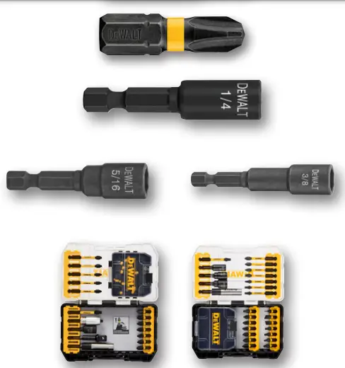
Accessories
| Accessories | ||||||||||
| Cat. No. | Qty / Carton | |||||||||
| DwA3HLDFT | 3IN IMPACT rEADY® HOLDEr | |||||||||
| DwA1PH2Ir2 | #2 Phillips Bit Tip (2 Pack) | |||||||||
| DwA1PH3Ir2 | #3 Phillips Bit Tip (2 Pack) | |||||||||
| Dw2221Ir | 1/4″ x 2-9/16″ IMPACT rEADY® MAGNECTIC NUT DrIVEr | |||||||||
| Dw2222Ir | 5/16″ x 2-9/16″ IMPACT rEADY® MAGNECTIC NUT DrIVEr | |||||||||
| Dw2223Ir | 3/8″ x 2-9/16″ IMPACT rEADY® MAGNECTIC NUT DrIVEr | |||||||||
| DwANGFT32SET | 32 PIECE NEXT GEN Ir FLEX TOrQ SET | |||||||||
| DwANGFT26SET | 26 PIECE NEXT GEN Ir FLEX TOrQ SET | |||||||||
Documents / Resources
| DEWALT DWANF DRILIT Self-Drilling Screws [pdf] Instruction Manual DWANF DRILIT Self-Drilling Screws, DWANF, DRILIT Self-Drilling Screws, Self-Drilling Screws, Drilling Screws, Screws |