![]() WDA033 Issue 3 Installation Guide
WDA033 Issue 3 Installation Guide
EBDHS-B-MB-CB-DD
Contents
EBDHS-B-MB-CB-DD High Bay Presence Detectors
Casambi DALI digital dimming, luminaire batten mounted, high bay/high level

Warning
This device should be installed by a qualified electrician in accordance withthe latest edition of the IEE wiring regulations.
Downloads and Videos
 https://cpelectronics.co.uk/cp/A033qr
Dimensions (mm)

Wiring
Dimming ouputs
DALI is not an SELV output and should be treated as if it is at mains potential. Use mains rated wiring.
Key
- Neutral
- Live
- 10A circuit protection
- Load
- DALI+ (white), DALI- (red)
- Live Out
Unswitched DALI load Wiring

Switched load Wiring

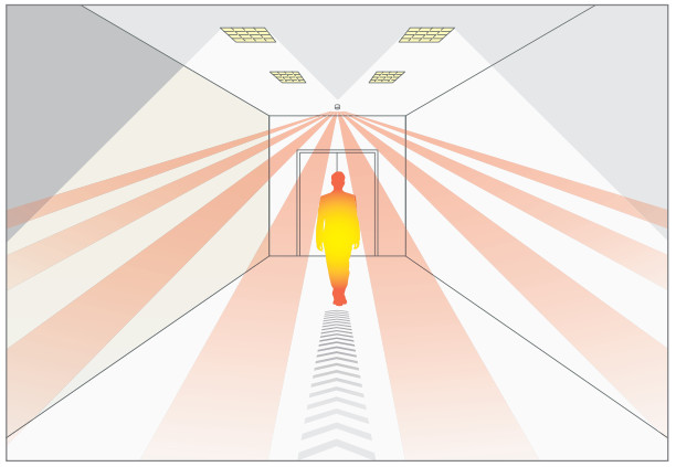
Detection pattern
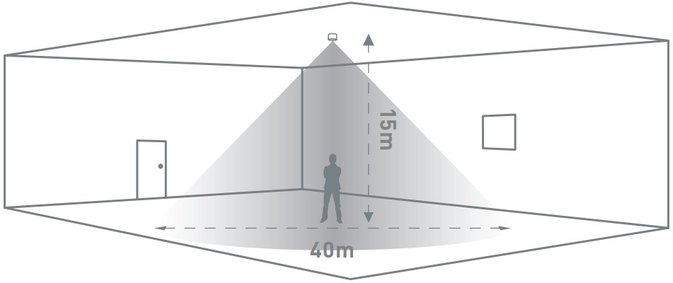
Walk across

| Height | Range Diameter |
| 15m | 40m |
| 10m | 26m |
| 6m | 16m |
| 3m | 9m |
Walk towards
| Height | Range Diameter |
| 15m | 30m |
| 10m | 20m |
| 6m | 12m |
| 3m | 8m |
Walk towards & walk across explained
 https://cpelectronics.co.uk/cp/wtaqr
Alignment marks

The sensor head has 4 alignment marks. These correspond to the 4 outer passive infrared sensors under the lens. Use these marks to align with aisles and corridors to ensure the best detection characteristics.
Masking shields

The EBDHS can be used with two clip-on masking shields, (supplied separately) enabling precise masking of the detection shape for aisles and corners as well as narrowing the detection diameter.
- Lateral trim pattern for slot style detection.
- Radial trim pattern for narrowing the detection diameter.
Ensure all infra-red (IR) programming is completed before affixing the masking shields to the detector.
Masking shield application
Aisles
Trim the masks laterally to reduce the detection width for aisles.
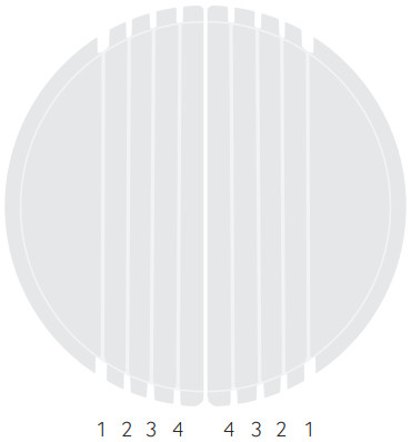
| a | b | c | d | e |
| 1 | wa 18m x 40m wt 13.5m x 30m |
wa 11.7m x 26m wt 9m x 20m |
wa 7.2m x 16m wt 5.4m x 12m |
wa 4m x 9m wt 3.6m x 8m |
| 2 | wa 12.8m x 40m wt 9.6m x 30m |
wa 8.3m x 26m wt 6.4m x 20m |
wa 5.1m x 16m wt 3.8m x 12m |
wa 2.8m x 9m wt 2.5m x 8m |
| 3 | wa 8.8m x 40m wt 6.6m x 30m |
wa 5.7m x 26m wt 4.4m x 20m |
wa 3.5m x 16m wt 2.6m x 12m |
wa 1.9m x 9m wt 1.7m x 8m |
| 4 | wa 4.4m x 40m wt 3.3m x 30m |
wa 2.8m x 26m wt 2.2m x 20m |
wa 1.7m x 16m wt 1.3m x 12m |
wa 0.9m x 9m wt 0.8m x 8m |
Key
a. Trim line
b. 15m Mounting height
c. 10m Mounting height
d. 6m Mounting height
e. 3m Mounting height
wa = walk across
wt = walk towards
Install shields to detector

Align trimmed shields with sensor head alignment marks and aisle.
Narrow detection
Trim the masks along radial lines to narrow the detection diameter.
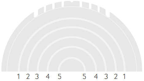
| a | b | c | d | e |
| 1 | wa 35.6m wt 26.7m |
wa 23.1m wt 17.8m |
wa 14.2m wt 10.6m |
wa 8m wt 7.1m |
| 2 | wa 25.2m wt 18.9m |
wa 16.3m wt 126m |
wa 10m wt 7.5m |
wa 5.6m wt 5m |
| 3 | wa 18m wt 13.5m |
wa11.7m wt 9m |
wa 7.2m wt 5Am |
wa 4m wt 3.6m |
| 4 | wa 12.8m wt 9.6m |
wa 8.3m wt 6.4m |
wa 5.1m wt 3.8m |
wa 2.8m wt 2.5m |
| 5 | wa 8.8m wt 6.6m |
wa 5.7m wt 4.4m |
wa 3.5m wt 2.6m |
wa 1.9m wt 1.7m |
Key
a. Trim line
b. 15m Mounting height
c. 10m Mounting height
d. 6m Mounting height
e. 3m Mounting height
wa = walk across
wt = walk towards
Install shields to detector

Align trimmed shields with sensor head alignment marks and aisle.
Sensor Configurations

Configure the sensor controls via the Casambi App from Apple App Store or Google Play Store.
For light regulation control, ensure that the setting below is made and allow for a few minutes to take effect:
[Use the full dim range] = enable
See CP Electronics Casambi Application Guide.
The communication range between two Casambi units is highly dependant on the surrounding and obstacles, such as walls and building materials. In indoor environments the range can be up to 30 m and in outdoor conditions up to 50 m. In the majority of applications Casambi units are only ever 5 to 6 meters away from each other to provide excellent reliability in the communication network.
Installation
This unit is designed for install as an integration to the stomer’s product.
- Do not site the unit where direct sunlight might enter the sensor.
- Do not site the sensor within 1m of any lighting, forced air heating or ventilation.
- Do not fix the sensor to an unstable or vibrating surface.
- Occupancy is best detected when the ambient temperature is different to that of the human body, thus, use within -20 to 35ºC ambient temperature.
Standard luminaire fitting
Wire in plugs & connect to detector

Key
- M20 nut
- IP spacer
IP luminaire fitting
Wire in plugs & connect to detector
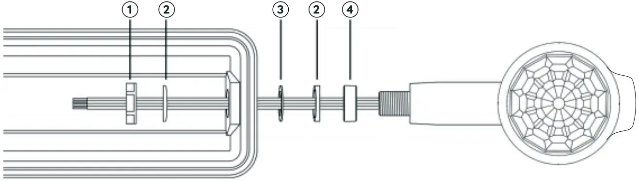
Key
- M20 nut
- 5° washer (optional)
- Silicone washer
- IP spacer
- Note: Use the 5° spacers where the luminaire has a draft angle.
- Ensure that the silicone washer and/or IP spacer are used to maintain IP rating.
Technical Data
| Part code | EBDHS-B-MB-CB-DD |
| Weight | 0.15kg |
| Supply voltage AC | 100-240 VAC +/- 10% |
| Supply frequency | 50/60Hz |
| Circuit Protection | ≤10A, MCB type B |
| Terminal capacity | 2.5mm² |
| Max switched load: | |
| Incandescent lighting | 10A |
| Fluorescent lighting | 4A |
| Compact fluorescent lighting | 4A |
| LED lighting | 4A |
| Resistive heaters | 10A |
| Load inrush rating | 90A for 340μs |
| SON lighting | Switch loads via a contactor |
| Max DALI dim load | Up to 10 |
| Cable specification | 5 x 1mm2 solid core PVC sheath 90ºC |
| Light detection range | 1-999 lux |
| Transceiver frequency | 2.4GHz ISM band |
| Transceiver power | Up to 4 dBm output power and -93 dBm RX sensitivity |
| Rated impulse voltage | 2500V |
| Purpose | Sensing control |
| Operational temperature | 0 to 50°C |
| Humidity | 5 to 95% non-condensing |
| Material (casing) | Flame retardant ABS |
| Insulation class | Class 2 |
| IP rating | 40 |
| Compliance |
| CP Electronics A Business unit of Legrand Electric Limited, Brent Crescent, London NW10 7XR, UK t. +44 (0)333 900 0671 [email protected] |
||
| www.cpelectronics.co.uk | Connect with us |
Due to our policy of continual product improvement CP Electronics reserves the right to alter the specification of this product without prior notice.
WDA033 Issue 3 Installation Guide, EBDHS-B-CB-MB-DD
A brand of![]() 21307
21307