![]() V22a / V34 / V34a
V22a / V34 / V34a
Hearing Loop Driver
 Installation& User Guide
Contacte has a policy of continuous product development, therefore small specification changes may not be reflected in this manual. Images, labels, packaging, accessories and product colours are subject to change without notice.
Contents
Product Overview
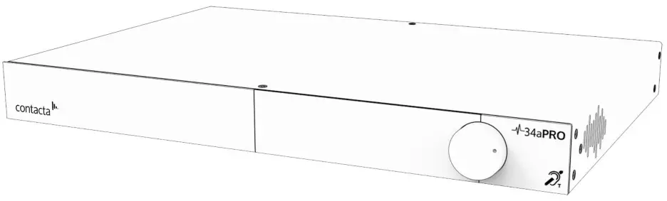
Our highly efficient and slimline V Series PRO range of hearing loop drivers (V22a, V34, and V34a) are suitable for medium to large facilities and venues.
The V34 is a high current hearing loop driver which powers hearing loops utilizing a single output. The V22a and V34a are dual output, high current hearing loop drivers with integral phase shifters for phased array configurations. These drivers have a Class-D amplifier output stage and an audio subsystem built around advanced digital systems including an ARM Cortex processor and dual DSPs.
Combined with a powerful CPU to ensure peak performance, the V Series PRO range provides self-monitoring and email alerts, remote setup over local area networks, guided hearing loop setup to make installation simple, and excellent speech and music reproduction.
Note: For large area hearing loop installation instructions, consult Contact’s Large Area Hearing Loop Installation Guide.
Components
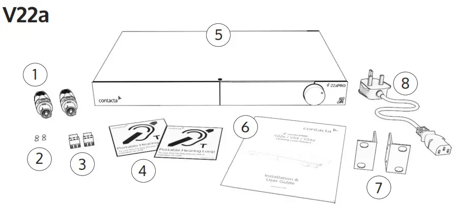
- NL4 Connector x2
- Rubber Feet x4
- 3.5mm Euroblock Connector x2
- Signage
- V22a Hearing Loop Driver
- Installation & User Guide
- Mounting Brackets
- IEC Power Lead
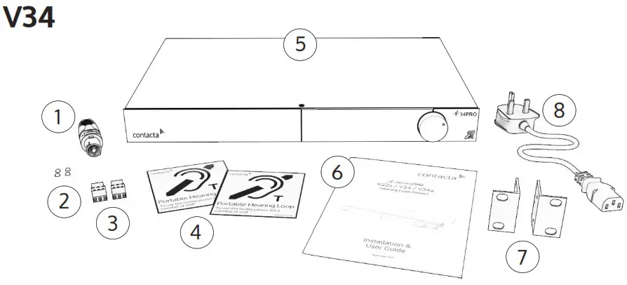
- NL4 Connector
- Rubber Feet x4
- 3.5mm Euroblock Connector x2
- Signage
- V34 Hearing Loop Driver
- Installation & User Guide
- Mounting Brackets
- IEC Power Lead
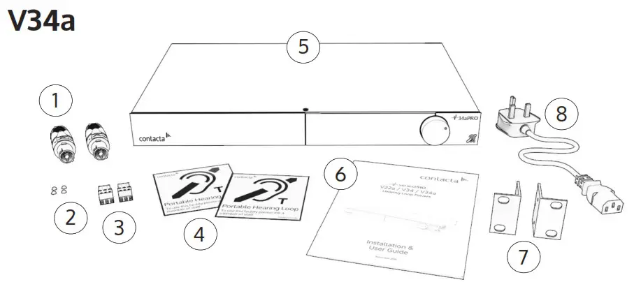
- NL4 Connector x2
- Rubber Feet x4
- 3.5mm Euroblock Connector x2
- Signage
- V34a Hearing Loop Driver
- Installation & User Guide
- Mounting Brackets
- IEC Power Lead
*Plug type varies by country.
Cable & Equipment: A length of loop cable determined by the loop design is also required. Hearing loop drivers also require additional equipment for audio feeds, such as a microphone or sound system.
Suitable Cable Lengths
The tables in this section show the approximate maximum cable lengths for differing maximum required currents.
Loop impedance (at 1.6kHz) should be less than the voltage capability of the driver (V22a: 22Vrms, V34: 34Vrms, V34a: 34Vrms) divided by the required current.
This achieves 400mA/m field strength at 1kHz.
V22a Single-Turn Hearing Loop (Metric)
| Current | 1A | 2A | 3A | 4A | 5A | 6A | 7A | 8A | ||
| Impedance | 21.3W | 10.7W | 7.1W | 5.3W | 4.3W | 3.6W | 3.0W | 2.7W | ||
| Cable Type | Cable Length | |||||||||
| Maximum Cable Length | Round Cable (AWG) | 1mm | 782m | 391m | 261m | 195m | 156m | 130m | 112m | 98m |
| 1.5mm | 917m | 458m | 306m | 229m | 183m | 153m | 131m | 115m | ||
| 2.5mm | 1031m | 515m | 344m | 258m | 206m | 172m | 147m | 129m | ||
| Flat Cable (Width) | 10mm | 580m | 290m | 193m | 145m | 116m | 97m | 83m | 73m | |
| 12.5mm | 1097m | 548m | 366m | 274m | 219m | 183m | 157m | 137m | ||
| 25mm | 1452m | 726m | 484m | 363m | 290m | 242m | 207m | 182m | ||
V22a Single-Turn Hearing Loop (Imperial)
| Current | 1A | 2A | 3A | 4A | 5A | 6A | 7A | 8A | ||
| Impedance | 36.0W | 18.0W | 12.0W | 9.0W | 7.2W | 6.0W | 5.1W | 4.5W | ||
| Cable Type | Cable Length | |||||||||
| Maximum Cable Length | Round Cable (AWG) | 18AWG | 2346ft | 1173ft | 782ft | 587ft | 469ft | 391ft | 335ft | 293ft |
| 14AWG | 3132ft | 1566ft | 1044ft | 783ft | 626ft | 522ft | 447ft | 392ft | ||
| Flat Cable (Width) | 18AWG (equivalent) | 2639ft | 1320ft | 880ft | 660ft | 528ft | 440ft | 377ft | 330ft | |
| 14AWG (equivalent) | 4171ft | 2085ft | 1390ft | 1043ft | 834ft | 695ft | 596ft | 521ft | ||
V22a Double-Turn Hearing Loop (Metric)
| Current | 1A | 2A | 3A | 4A | 5A | 6A | 7A | 8A | ||
| Impedance | 21.3W | 10.7W | 7.1W | 5.3W | 4.3W | 3.6W | 3.0W | 2.7W | ||
| Cable Type | Cable Length | |||||||||
| Max Cable Length | Round Cable (AWG) | 1mm | 568m | 284m | 189m | 142m | 114m | 95m | 81m | 71m |
| 1.5mm | 614m | 307m | 205m | 154m | 123m | 102m | 88m | 77m | ||
| 2.5mm | 645m | 323m | 215m | 161m | 129m | 108m | 92m | 81m | ||
| Flat Cable (Width) | 10mm | 508m | 254m | 169m | 127m | 102m | 85m | 73m | 63m | |
| 12.5mm | 785m | 392m | 262m | 196m | 157m | 131m | 112m | 98m | ||
| 25mm | 929m | 465m | 310m | 232m | 186m | 155m | 133m | 116m | ||
V22a Double-Turn Hearing Loop (Imperial)
| Current | 1A | 2A | 3A | 4A | 5A | 6A | 7A | 8A | ||
| Impedance | 36.0W | 18.0W | 12.0W | 9.0W | 7.2W | 6.0W | 5.1W | 4.5W | ||
| Cable Type | Cable Length | |||||||||
| Maximum Cable Length | Round Cable (AWG) | 18AWG | 2649ft | 1324ft | 883ft | 662ft | 530ft | 441ft | 378ft | 331ft |
| 14AWG | 3027ft | 1514ft | 1009ft | 757ft | 605ft | 505ft | 432ft | 378ft | ||
| Flat Cable (Width) | 18AWG (equivalent) | 3203ft | 1601ft | 1068ft | 801ft | 641ft | 534ft | 458ft | 400ft | |
| 14AWG (equivalent) | 4202ft | 2101ft | 1401ft | 1050ft | 840ft | 700ft | 600ft | 525ft | ||
V34 / V34a Single-Turn Hearing Loop (Metric)
| Current | 1A | 2A | 3A | 4A | 5A | 6A | 7A | 8A | 9A | 10A | 11A | 12A | ||
| Impedance | 21.30W | 10.65W | 7.10W | 5.33W | 4.26W | 3.55W | 3.04W | 2.66W | 3.57W | 3.21W | 2.92W | 2.68W | ||
| Cable Type | Cable Length | |||||||||||||
| Max Cable Length | Round Cable (AWG) | 1mm | 1146.1m | 573.0m | 382.0m | 286.5m | 229.2m | 191.0m | 163.7m | 143.3m | 127.3m | 114.6m | 104.2m | 95.5m |
| 1.5mm | 1379.2m | 689.6m | 459.7m | 344.8m | 275.8m | 229.9m | 197.0m | 172.4m | 153.2m | 137.9m | 125.4m | 114.9m | ||
| 2.5mm | 1550.7m | 775.3m | 516.9m | 387.7m | 310.1m | 258.4m | 221.5m | 193.8m | 172.3m | 155.1m | 141.0m | 129.2m | ||
| Flat Cable (Width) | 10mm | 872.7m | 436.3m | 290.9m | 218.2m | 174.5m | 145.4m | 124.7m | 109.1m | 97.0m | 87.3m | 79.3m | 72.7m | |
| 12.5mm | 1650.4m | 825.2m | 550.1m | 412.6m | 330.1m | 275.1m | 235.8m | 206.3m | 183.4m | 165.0m | 150.0m | 137.5m | ||
| 25mm | 2184.9m | 1092.4m | 728.3m | 546.2m | 437.0m | 364.1m | 312.1m | 273.1m | 242.8m | 218.5m | 198.6m | 182.1m | ||
V34 / V34a Single-Turn Hearing Loop (Imperial)
| Current | 1A | 2A | 3A | 4A | 5A | 6A | 7A | 8A | 9A | 10A | 11A | 12A | ||
| Impedance | 21.30W | 10.65W | 7.10W | 5.33W | 4.26W | 3.55W | 3.04W | 2.66W | 3.57W | 3.21W | 2.92W | 2.68W | ||
| Cable Type | Cable Length | |||||||||||||
| Max Cable Length | Round Cable (AWG) | 18AWG | 1105.5ft | 552.7ft | 368.5ft | 276.4ft | 221.1ft | 184.2ft | 157.9ft | 138.2ft | 122.8ft | 110.5ft | 100.5ft | 92.1ft |
| 14AWG | 1476.0ft | 738.0ft | 492.0ft | 369.0ft | 295.2ft | 246.0ft | 210.9ft | 184.5ft | 164.0ft | 147.6ft | 134.2ft | 123.0ft | ||
| Flat Cable (Width) | 18AWG (equiv.) | 1243.6ft | 621.8ft | 414.5ft | 310.9ft | 248.7ft | 207.3ft | 177.7ft | 155.4ft | 138.2ft | 124.4ft | 113.1ft | 103.6ft | |
| 14AWG (equiv.) | 1965.2ft | 982.6ft | 655.1ft | 491.3ft | 393.0ft | 327.5ft | 280.7ft | 245.6ft | 218.4ft | 196.5ft | 178.7ft | 163.8ft | ||
V34 / V34a Double-Turn Hearing Loop (Metric)
| Current | 1A | 2A | 3A | 4A | 5A | 6A | 7A | 8A | 9A | 10A | 11A | 12A | ||
| Impedance | 32.1W | 16.0W | 10.7W | 8.0W | 6.4W | 5.3W | 4.6W | 4.0W | 3.6W | 3.2W | 2.9W | 2.7W | ||
| Cable Type | Cable Length | |||||||||||||
| Max Cable Length | Round Cable (AWG) | 1mm | 855m | 427m | 285m | 214m | 171m | 142m | 122m | 107m | 95m | 85m | 78m | 71m |
| 1.5mm | 924m | 462m | 308m | 231m | 185m | 154m | 132m | 116m | 103m | 92m | 84m | 77m | ||
| 2.5mm | 971m | 485m | 324m | 243m | 194m | 162m | 139m | 121m | 108m | 97m | 88m | 81m | ||
| Flat Cable (Width) | 10mm | 764m | 382m | 255m | 191m | 153m | 127m | 109m | 95m | 85m | 76m | 69m | 64m | |
| 12.5mm | 1181m | 590m | 394m | 295m | 236m | 197m | 169m | 148m | 131m | 118m | 107m | 98m | ||
| 25mm | 1398m | 699m | 466m | 350m | 280m | 233m | 200m | 175m | 155m | 140m | 127m | 117m | ||
V34 / V34a Double-Turn Hearing Loop (Imperial)
| Current | 1A | 2A | 3A | 4A | 5A | 6A | 7A | 8A | 9A | 10A | 11A | 12A | ||
| Impedance | 36.0W | 18.0W | 12.0W | 9.0W | 7.2W | 6.0W | 5.1W | 4.5W | 4.0W | 3.6W | 2.9W | 2.7W | ||
| Cable Type | Cable Length | |||||||||||||
| Max Cable Length | Round Cable (AWG) | 18AWG | 2649ft | 1324ft | 883ft | 662ft | 530ft | 441ft | 378ft | 331ft | 294ft | 265ft | 241ft | 221ft |
| 14AWG | 3027ft | 1514ft | 1009ft | 757ft | 605ft | 505ft | 432ft | 378ft | 336ft | 303ft | 275ft | 252ft | ||
| Flat Cable (Width) | 18AWG (equiv.) | 3203ft | 1601ft | 1068ft | 801ft | 641ft | 534ft | 458ft | 400ft | 356ft | 320ft | 291ft | 267ft | |
| 14AWG (equiv.) | 4202ft | 2101ft | 1401ft | 1050ft | 840ft | 700ft | 600ft | 525ft | 467ft | 420ft | 382ft | 350ft | ||
Driver Area Coverage
Note: A full site survey of an installation area is recommended for optimal loop design.
Perimeter Loops
Perimeter loop areas detailed in the table on page 11 are valid only when the following conditions are met:
- Area is at the maximum current the driver is capable of delivering without voltage clipping at 1.6KHz
- Loop layout is designed to achieve 0dB in the centre
- 25mm x 0.1mm flat copper cable
- Loop is installed in the floor
- Listening height 1.2m (large perimeter loops may have areas where the actual signal level is higher than required)
Phased Array Loops
Phased array loop areas detailed in the table on page 11 are valid only
when the following conditions are met:
- Area is at the maximum voltage the driver is capable of delivering without voltage clipping at 1.6KHz
- Layout of 3m segment widths
- 25mm X 0.1mm flat copper cable is used
- Loop is installed in the floor
- Listening height 1.2m
- Medium metal loss = 6dB
| Area | ||||||
| Voltage | Current | 1:1 | 1:2 | 1:3 | ||
| Perimeter loops | ||||||
| V34 Pro | 34.0V | 12.0A | 702.25m² | 882.00m² | 1200.00m² | |
| Phased array (no metal loss) | ||||||
| V22a Pro | 22.6V | 8.0A | 1024.00m² | 1104.50m² | 1160.33m² | |
| V34a Pro | 34.0V | 12.0A | 1521.00m² | 1740.50m² | 1680.33m² | |
| Phased array (medium metal loss) | ||||||
| V22a Pro | 22.6V | 8.0A | 441.00m² | 480.50m² | 588.00m² | |
| V34a Pro | 34.0V | 12.0A | 676.00m² | 840.50m² | 867.00m² | |
Connections
Rear Panel Connections

- Power Supply Input – The primary method of isolating the amplifier from the mains supply is to disconnect the mains plug. Ensure that the mains plug remains accessible at all times. Unplug the AC power cord from the AC outlet if the unit will not be used for several months or more.
- Network Input – Ethernet port for setup and remote monitoring.
- Input A – Microphone or line in via 3 Pin Euroblock or XLR.
- Input B – Microphone or line in via 3 Pin Euroblock or XLR.
- Line Output – XLR port for connections with multiple drivers.
- USB – Storage transfer port.
- Loop A Output – NL4 port for Loop A.
- Loop B Output – NL4 port for Loop B.
Connection Examples

Using the System
Startup

V Series PRO drivers perform a series of tests when powered on. The Contacte logo will appear and driver will therefore take between 40 to 60 seconds to become active.
Fault Detected
If a fault is detected, the Attention symbol will appear on the top right of the screen (![]() ) along with an error message:
) along with an error message:
- Open Circuit [Primary/Secondary Loop]: See Connections on page 12 or consult the Contacte Large Area Loop Installation Guide to ensure the hearing loop is correctly installed and connected.
- Short Circuit [Primary/Secondary Loop]: See Connections on page 12 or consult the Contacte Large Area Loop Installation Guide to ensure the hearing loop is correctly installed and connected.
The start-up sequence will be halted. Power should be removed and reapplied to the driver once the fault has been addressed.
Loop Attenuation

If the ‘ATTN’ (Loop Attenuation) symbol ( ) appears on the screen, the driver has detected that due to the characteristics of the loop(s) connected it will be unable to deliver maximum rated current without clipping at 1.6Kz. Maximum current will therefore be attenuated.
Front Panel Overview
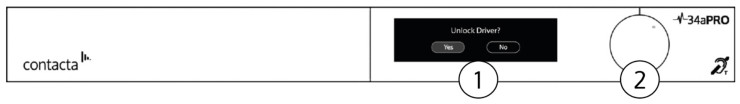
- Display Screen – Displays menu and adjustment options.
- Control Dial – Used to unlock the driver and make a range of system adjustments. Rotate the dial clockwise or counter-clockwise to make a selection, then press to confirm any adjustments.
Note: When using V Series PRO menus, selecting “Return” sends the user to a previously displayed screen. Selecting “Exit” will send them to the main menu.
Locking/Unlocking the Hearing Loop Driver

Unlock the Driver
- To unlock the hearing loop driver, press the control dial, and when prompted “Unlock driver?” click “Yes.”
- Enter the passcode 2239:
a. Rotate the control clockwise to select the first required digit.
b. Press the control dial in to select the digit.
c. Repeat steps (a) and (b) until all the digits have been selected.
Note: Entering the wrong code returns the hearing loop driver to the lock screen.
When the control dial is not used for half an hour, the hearing loop driver will automatically lock.
Signal Activity Indicators
When the driver is locked, the “ABC” indicators on the bottom left of the screen display signal activity on the driver inputs.
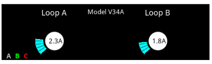
Each letter are shown in green, yellow, or red, corresponding to low, good, or high signal levels respectively.
The “A” and “B” indicators show the levels of the A and B inputs. This is the level after the corresponding input gain control, but before the AGC. If the AGC is not enabled, it is important that A or B are indicating acceptable levels. If the AGC is enabled, this is less important as the AGC will compensate for a wide range of levels.
The “C” indicator shows the signal level within the signal chain after the AGC, if enabled, has been applied. It is normal to see activity here, at least on program peaks.
If the driver appears to stop working, and no changes have been made, the ABC indicators will assist the user by showing whether the inputs are active.
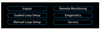
Main Menu
After being unlocked, the hearing loop driver will display the main menu.
Inputs
Selecting Inputs from the main menu opens the following screen:
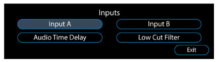
- Input A – Adjust connections to Input A.
- Input B – Adjust connections to Input B.
- Audio Time Delay – Sync audio across large distances to compensate for latency.
- Low Cut Filter – Audio filter for when there is low frequency background noise in the surrounding environment of a loop.
Input A/B
- Menus for Input A and Input B are functionally identical. Selecting either Input A or Input B opens the following screen:
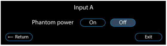
- Turning on Phantom Power sends power to a connected microphone via the selected input. When either Input A or Input B has enabled this function, a symbol will appear on the left of the display (see page 51 for Notification Guide).
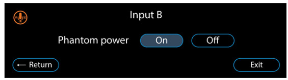
- Once you have made a selection on the Phantom Power screen, the driver will display the following screen:
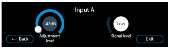 • Adjustment Level – Displays the input attenuation level (0db to -47dB). Selecting this circle allows attenuation level adjustment.
• Signal Level – When optimum Adjustment Level has been achieved, “Good” will display consistently (though peak levels may flash to “Low or “High”). Consistent display of “Low” or ”High” means the level is incorrect and automatic gain control cannot operate.
Audio Time Delay
Selecting Audio Time Delay from Inputs opens the following screen:

In theatres, stadiums, and other large venues, sound sent from speakers will be impacted by the speed of sound, whereas audio sent through a hearing loop will reach a user instantly. This means the two sounds must be aligned or users will hear a constant echo.
Select the screen’s circle to adjust syncing and compensate for latency.
Low Cut Filter
Selecting Low Cut Filter from Inputs opens the following screen:

This feature removes low frequency sounds from the hearing loop when background noise such as air conditioners might impact users.
Select either 150Hz or 180Hz if required and a green ‘LCF’ (Low Cut Filter) symbol will be displayed on the left.
Guided Loop Setup
Guided Loop Setup ensures that hearing loops achieve optimum field strength,* ideal frequency response, and avoid clipping.
Only begin Guided Loop Setup once the connected hearing loop cable has been laid in place and all relevant connections have been made (see page 12).
*This is dependant on correct loop design and metal loss.
Required for Setup
- FSM – Contacte Field Strength Meter (IL-CONTACTA-FSM)
- Tripod or similar for mounting the FSM is recommended
Begin the Setup
Begin the Guided Loop Setup by selecting it from the driver’s main menu, and when prompted select “Yes” from the following screen:

For large area hearing loop cable installation instructions, consult Contact’s Large Area Hearing Loop Installation Guide.
Note: The guided loop setup will optimise the loop signal at the point used to take the measurement. Therefore, there may be variations in the signal coverage where no measurements have been taken and fed into the driver.
Stage 1: High Frequency Compensation
High Frequency Compensation will be suggested by the driver when measurements in this section indicate metal in the surrounding environment impacts the hearing loop’s signal quality.
- Select “Yes” when prompted by the following screen:
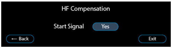
- The driver will begin outputting a pink noise signal at a low level (1A on peaks) to allow accurate setup. The following screen will be displayed, with a symbol on the top right indicating “Signal On”:
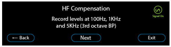
- Note the hearing loop’s field strength at 100Hz, 1KHz, and 5KHz using the Contacta Field Strength Meter (IL-CONTACTA-FSM) set at the 3rd octave band pass setting. Once this is completed, select “Next” on the display to turn off the signal.
- Enter the three levels into the hearing loop driver. The “Backspace” button will become a “Next” button when the correct number of digits have been entered for each value:

- When the three levels have been entered, one of following options will be displayed (see next page):
5a. If the values at 100Hz and 5KHz are within +/-3db of the value measured at 1KHz, this section is complete. Select “Next”: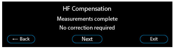 5b. If the driver has calculated that High Frequency Compensation is required, it will ask whether to apply this correction. Selecting “Yes” is recommended.
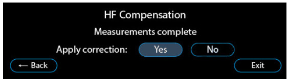 5c. If the driver cannot provide ideal High Frequency Compensation, it will ask whether to apply the maximum adjustment available. Selecting “Yes” is recommended.
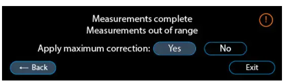
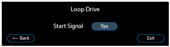
Stage 2: Loop Drive
- Select “Yes” when prompted by the following screen:
 The driver will begin outputting a 1KHz sinewave signal at a low level (2Arms) to allow accurate setup.
 - The following screen will be displayed, with a symbol on the top right indicating “Signal On”:
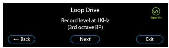
- Note the hearing loop’s field strength at 1KHz using the Contacte Field Strength Meter (IL-CONTACTA-FSM) set at the 3rd octave band pass setting. Once this value has been noted, select “Next” on the display to turn off the signal.

- Enter the noted level into the hearing loop driver.
- One of following three options will be displayed:
5a. If the driver has calculated the ideal peak current to achieve 0dB, the following screen will appear and this section is complete. Select “Apply this level”: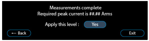 5b. If the driver cannot deliver the current required to achieve 0dB it will display the following screen:
Select “Yes” when asked to apply the maximum unclipped current.
5c. If the ideal current is greater than is possible (due to the characteristics of the loop(s) connected being unsuitable to deliver maximum rated current without clipping at 1.6Kz), the maximum current will be attenuated and the maximum value will be
displayed: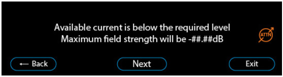 Select “Next”. The driver will make adjustments to achieve the strongest maximum field strength possible.
Stage 3: Loop Uniformity
- Select “Yes” when prompted by the following screen:
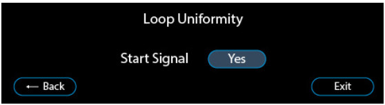 The driver will begin outputting a 1Arms at 1KHz sinewave signal at a level below the calculated current required to hit 0dB field strength.
 - The following screen will be displayed, with a symbol on the top right indicating “Signal On”:

- Record field strength at various locations in the hearing loop using the Contacte FSM set 1KHz 3rd octave band pass setting. These details will be required in Compliance Certificate documents. Then, select “Next”.
Stage 4: Completion
- Select “Yes” when prompted by the following screen to complete the Guided Loop Setup to save settings:

Manual Loop Setup
Note: Most users will obtain the best performance from a V-Pro driver using the Guided Loop Setup. Manual setup mode can render an installation non-compliant with standards if done incorrectly. Enter this menu only if you are competent and qualified to proceed with Manual Loop Setup.
Begin Manual Loop Setup by selecting the option from the driver’s main menu.
Note: For large area hearing loop cable installation instructions, consult Contact’s Large Area Hearing Loop Installation Guide or design software suites.
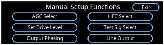
Manual setup allows the selection of the following functions:
- AGC Select: Enable or disable the Automatic Gain Control.
- HFC Select: Set High Frequency Compensation (metal correction).
- Set Drive Level: Set the Output Drive Level.
- Test Sig Select: Enable the internal Test Signal Generator.
- Output Phasing: Select non-standard output phasing (phased drivers only).
- Line Output: Set the level at the line output XLR jack.
AGC (Automatic Gain Control) Select
This screen allows automatic gain control to be disabled or enabled.
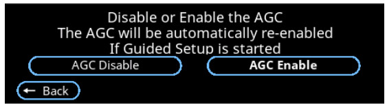
If the AGC is disabled the input gain may need to be adjusted on the Inputs setting screen. This is particularly the case if the input level is low in relation to the input gain and was previously being normalised by AGC.
Note: If Guided Setup is subsequently used after Manual Setup, AGC will be automatically re-enabled.
HFC Select
This screen allows high-frequency compensation to be adjusted from 1 (weak) to 7 (strong).
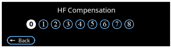
HFC is required when metal in the surrounding environment impacts the hearing loop’s signal quality.
Set Drive Level
This screen allows the current in the primary loop to be adjusted.
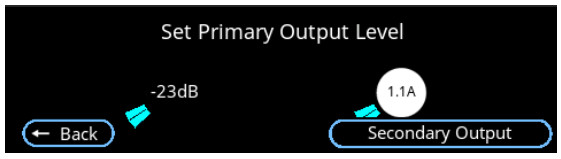
The maximum current will be limited to the specified level for the driver, and no attempt should be made to exceed this. If the driver is a phased unit, it will be possible set the secondary output (bottom right of the screen).
Note: Setting the driver to output currents in excess of the specified value will void the warranty.
If the driver is being set up from a remote device, increase the current gradually by clicking at the start of the level setting arc.
Phased Drivers Only: Secondary Output
This screen allows the current in the secondary loop in phased drivers to be adjusted.
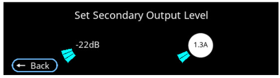
In phased drivers it is important to set primary and secondary currents to similar values or the advantages of a phased system will be lost.
Test Sig Select
This screen allows the internal test signal generator to drive output stages.
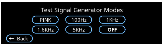
The internal signal chain is driven at relatively low level, meaning this function is not intended for setting final output levels. However, levels of the signals at different frequencies are well matched, making the function suitable for frequency response testing.
All selections other than “Off” will have the following additional effects on the driver:
- The internal cooling fans will run up to full speed.
- The normal input signal will be disconnected.
- The loop continuity test signal will be disabled to allow accurate current measurements.
Effects listed above will be cancelled when the TSG mode is set to “Off” or when Manual Setup mode is exited.
The TSG signal will remain on while within the Manual Setup functionality unless manually switched off. This is to allow manual adjustment of HF compensation.
Output Phasing
This screen determines the phase relationship between the primary and secondary outputs on phased drivers.
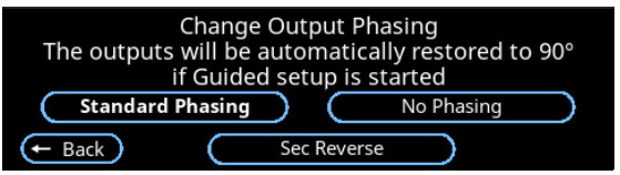
In phased systems it is vital that the output phase relationship remains set to Standard Phasing. The driver will not act as a proper phased device in any other mode.
There are two other phasing options:
- No Phasing” causes the two outputs to operate in phase with each other. The driver is no longer phased in the manner required to produce uniform field coverage
- Sec Reverse” inverts the phase of the secondary output. This is the same as reversing the electrical connections to one (but not both) of the driver outputs of an un-phased driver.
Line Output
This screen sets the output level of the balanced line output XLR jack on the rear of the driver.
Note: Line Output Level should usually remain at 1.00 and only be reduced if advised by an educated installer.
This output is not processed by the AGC to eliminate the possibility of “double AGC-ing” by devices further down the audio chain.
The signal level is the sum of the signal at inputs A and B. This means that the gains of the two inputs must be set to give an adequate output level at the line output connector.
The phase relationship between the Line output and the driver loop outputs is not guaranteed.
Diagnostics
Selecting Diagnostics from the main menu opens the following screen:
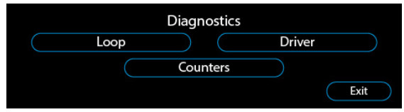
Loop
Selecting Loop from the Diagnostics menu opens the following screen:
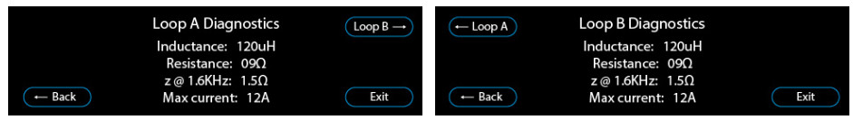
- Loop inductance and resistance are values measured when the driver powers on.
- Hearing loop impedance at 1.6KHz (“[email protected]) is calculated from the measured inductance and resistance.
- Maximum current is calculated from the driver voltage divided by the impedance at 1.6KHz.
- If impedance exceeds the limit the maximum current will be attenuated to prevent clipping.
Driver
Selecting Driver from the Diagnostics menu opens the following screen:
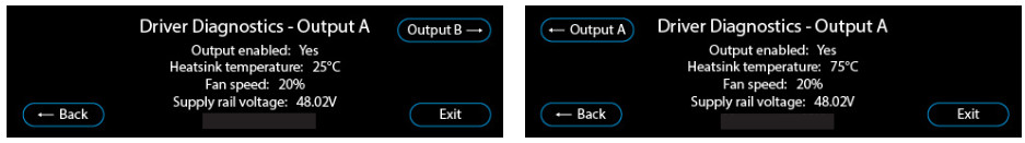
The following data in Driver is for information only:
- Output enabled (Yes/No)
- Heatsink temperature
- Fan speed
- Supply rail voltage
Counters
Selecting Counters from the Diagnostics menu opens the following screen:

Counters logs the number of times these events have occurred in the lifetime of the driver:
- Power cycles – Power has been recycled.
- Clipping – Voltage clipping has been detected.
- Overtempt – Internal temperature has exceeded limits.
- Overcurrent – Output current has exceeded limits.
- Loop o/c – Open circuit loop(s) have been detected.
Service
Selecting Service from the main menu opens the following screen:
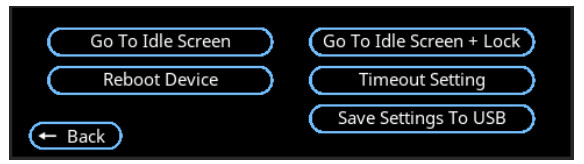
- Go to Idle Screen: The driver displays an idle screen. An unlock code will not be required to make adjustments/change settings.
- Go to Idle Screen + Lock: The driver displays an idle screen. An unlock code will be required to make adjustments/change to settings.
- Time out setting: Adjust the time before the driver displays an idle screen from between 0 (no return to idle screen) to 60 minutes. This is adjustable in 1-minute steps.
- Reboot Device: Restart the driver. Confirmation (Yes/No) is requested.
- Save settings to USB: The driver saves all user settings to a USB flash drive (see page 33).
Save/Load Settings to USB Flash Drive
Automatic Saving
Settings changed in the Guided Setup or Manual Loop Setup are updated once the user completes the setup. Completing the setup will return to the main menu screen where all settings are saved locally.
USB Flash Drive – Saving and Loading
- If a USB flash drive is connected to the driver, it will scan for a valid save file. The save file name must match the driver’s model (V22a, V34, or V34a).
- If a valid save file is located on the USB flash drive, the driver will ask if these settings should be loaded:
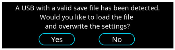 • Selecting “Yes” will load the file and overwrite settings saved on the driver, followed by a confirmation message:
 • Selecting “No” will return the driver to the main menu.
 - To save settings to a USB flash drive, select “Save settings to USB” from the service menu. If no previous save file is located on the USB flash drive, the driver will save current settings and display the following message:
 Selecting “Menu” will return to main menu.
If a valid save file already exists on the USB flash drive, the following message will be displayed instead: • Selecting “Yes” will update the settings on the USB flash drive and display a message confirming that all settings have been saved.
• Selecting “No” will return the driver to the main menu.
System Updates
There are 2 types of system updates:
- Software updates (see page 35)
- Disk image updates (see page 36)
Software updates require the following 4 files to be placed in the root (top-level/default) directory of a USB connected to the driver:
- pn1001-image-imx6ul-var-dart.ubi
- pn1001-image-imx6ul-var-dart.ubi.sig
- update.sh
- update. sh. sig
Disk image updates requires the same 4 files as the software update and an 4 additional files (for a total of 8 files):
- SPL-nand
- SPL-nand. sig
- u-boot. imgnand
- u-boot. img-nand. sig
The average update (software or disk image) takes three minutes to both finish installation and restart the system.
Note: Update related screens do not timeout to idle screens.
Software Updates – USB
Note: The driver software should be updated prior to installation. Drivers already connected to a hearing loop should not be updated as this may cause settings to alter.
Software updates can be run from a connected USB without any risk to the driver. If a USB is removed midway, the device will restart while maintaining the previously installed version of the software.
Generic V PRO software updates work for all drivers in the range.
When a USB has been connected, relevant updates will be automatically completed for any model (V22a, V34, V34a) in the range.
- To install a software update, connect a USB device which contains the required files.
- Select “Yes” when prompted by the following screen:
 3a. If the USB’s files are valid, the driver will begin install the update before automatically restarting. The following screen will appear:
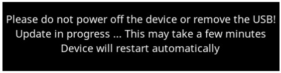 3b. If any of the USB’s files are not valid, the driver will display the following screen:
 3c. If the above error message appears, ensure the USB drive contains only update files – other files on the drive will prevent the update from occurring. We recommend using a formatted USB drive.
Disk Image Updates – USB
If the driver is low on memory, there will be a warning if a disk image update is attempted as the driver could be damaged if the USB is then removed mid-update. The user will be asked to confirm that they are aware of this risk.
- To install a disk update, connect a USB device which contains the required files.
- Select “Yes” when prompted.
- The driver will scan the USB’s files.
3a. If all files are valid, the driver will begin install the update and display this screen to the user before automatically restarting. The following screen will be displayed: 3b. If the USB’s files are not valid, the following screen will display:
 3c. If the above error message appears, ensure the USB drive contains only update files – other files on the drive will prevent the update from occurring. We recommend using a formatted USB drive.
Remote Monitoring
The driver’s user interface (settings screen) is accessed via a Local Area Network (LAN) connection and a browser on a laptop or smartphone. This allows easier adjustment of the driver on site during setup.
Accessing remote monitoring
- For browser access the IP address of the driver may be discovered from the Remote Monitoring screen. To access this, select Remote Monitoring from the main menu to open the following screen:

- The driver’s IP address will be displayed. Enter this string of numbers into the browser of your laptop or smartphone to externally access the driver’s display. This screen also shows the MAC address and PIN number which are needed when registering
the driver on the cloud dashboard. - Press “Connect” when prompted.
- Enter “root” as the password when prompted.
Changing network settings
To change network settings, click “Settings” from the “remote monitoring” screen.

Here you can choose the IP address assignment method to be via DHCP or statically set.
By default, DHCP is used. To set an IP address manually, you will need the following information: IP address, Subnet Mask and Gateway.
By clicking “Static” the driver will ask for this information. A Static IP address should only be assigned if the network IP address allocation is fully understood.
Contacte Dashboard
The Contacte Dashboard is a platform that allows users to set up email alerts; these alerts will keep users informed about the status of their driver and inform them if any issues occur.
The Contacte Dashboard also allows users to track the health of their V PRO drivers over the internet. All data is logged into the Contacta Dashboard cloud system which can then be viewed on any device.
Settings of drivers can also be managed remotely; for example, where notification emails are sent to, and the recorded locations of the devices.
Getting Started
Using the system is a two-part process to get set up:
- Register the device (once per device).
- Register an installer account on the dashboard (one-time set up).
The first part is to register drivers on the logging platform. You do this once per device while you are installing the device on-site. Simply fill out a form which describes the client name, location, and contact details for notifications.
Then, register an account on the Contacta Dashboard platform. This is a one-time process to verify your installer email address and set up an account password.
After that, all new devices registered to that installer email will automatically be managed in your Contacta Dashboard account.
Device Registration
- Register a device during the on-site device installation process.
During the setup of the device you will be provided with:
• The mac address of the device
• A 4-digit access control pin number - Visit the Contacta Dashboard platform setup page: https://log.contactadashboard.com/login.php
- Log in with your mac / validation number:

- After logging in, complete the following form. Ensure that you are using the same installer email address on all devices that you wish to manage from the same dashboard account.
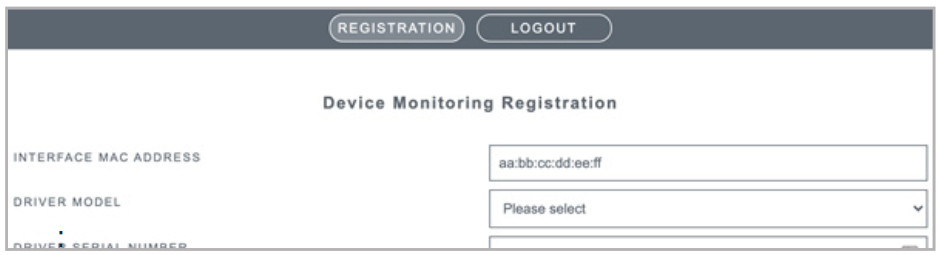 A confirmation email will be sent to all email addresses you listed (installer, plus any customer notification email addresses used).
Note: If a wrong email address is used, come back to this form at any time and re-register the device. This will overwrite the previously registered details. - Confirm with each recipient that the emails have been received and were not caught in spam filters.
Ask any relevant email management companies to ensure emails from the Contacte address are whitelisted. If you have opted to send notifications to clients, pass this information on to them so that they can whitelist it.
Account Registration
All registered drivers are managed at: https://www.contactadashboard.com/
- When accessing the Contacte Dashboard a login page will appear:
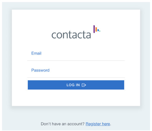
- Click the “Register here” link below the login box.
- Fill the form using the installer email address entered in the previous device registration form (see page 40).
- Once this form is completed, verify your email address.
- A verification link will be sent to the installer email address. Click the link to verify ownership of your email system.
- Log in to the Contacte Dashboard platform.
Note: Your account will stay logged in until you log out. This makes it convenient for you to quickly get back into the dashboard and check on a device. To log out, use the button in the top right-hand corner of the dashboard.
Device Management
The following device summary page appears on the homepage of the Contacte Dashboard:
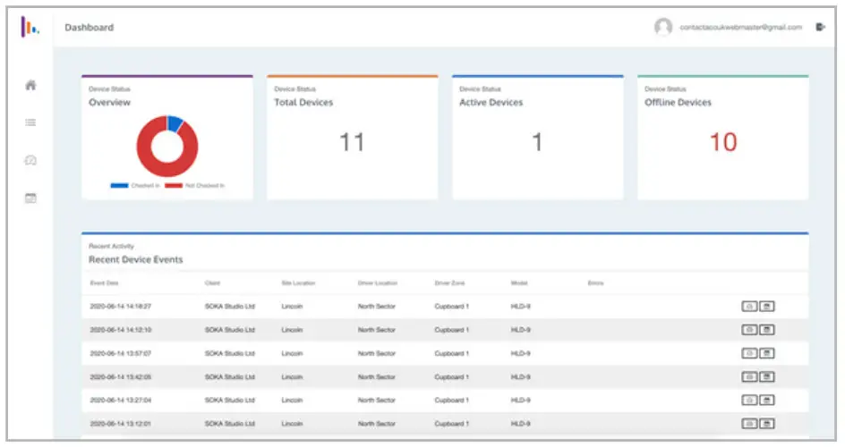
This page is divided into four sections:
- The navigation menu down the left-hand side.
- Four panels showing the device check in stats.
- A list of recent events generated by your devices.
- The account information in the top right.
The navigation menu lets you access all of the features of the site.
On small screens this may be hidden by default. Tap the menu button to expand it:
![]() Dashboard
Dashboard
 The first option is the Device Summary page (the home page):
 The third icon allows fast navigation to device settings pages:
 The fourth icon provides detailed device history, temperature and health information:
 Device Check-In Stats
At the top of the main page is an overview of all devices registered on the system:

A device is classed as offline if it hasn’t logged information into the cloud for more than 1 hour.
If you see red notices in the “Offline Devices” section noting drivers that should be online, any relevant hearing loop drivers must be assessed in person.
Recent device events
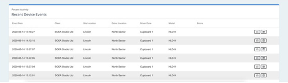
Recent device events lists any recent activity of registered drivers.
Registered devices
The registered devices page lists all devices registered to the current installer email account.
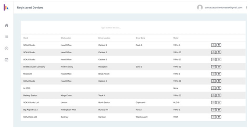
Filter devices using the filter function in the header of the table.
Within the “type to filter devices…” text box, simply type any identifying characteristic of the device.
For example, based on the screenshot above, typing “soka” would filter to all devices registered to the client “SOKA Studio”; or instead, filter a certain site by typing something like “head office”. Data can also be matched from the driver location, driver zone and model columns.
If the device is currently in a fault or caution error state, then the row will be highlighted in red or amber.
The last column has two shortcut buttons which will navigate you to the pages described in the next section:
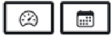 The left icon takes you to the device settings page.
- The right icon takes you to the device history page.
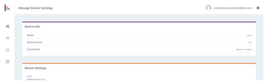
Device Settings
The device settings page shows the device info in the top panel. These are fixed fields which were specified at the devices registration and do not change.
The second panel contains the device settings. Manage the client and device location details here, plus set up the email addresses that any alerts are sent to.
To add multiple emails into the email notifications field, type an email address followed by a space. To remove an email address click the grey x on the right of each email tag.
To make changes to this section simply type the new details into the page, then scroll to the bottom of the page, and press the Update Settings button:

Note: If you want to completely disable email alerts for a device you can do a combination removing all of the email tags in this screen and then setting the “Send Alerts To” field to “Client”.
Device History
The device history page shows the entire history of that device.
This includes a panel at the top which shows the information that you have configured inside the device settings page:
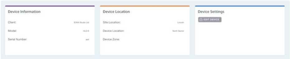
There is also a button to navigate back to the Device Settings page.
Just click Edit Device to make changes to that device.
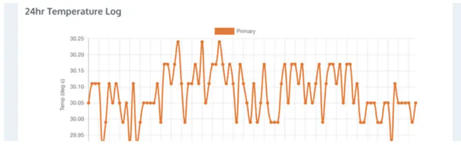
Further down a graph of its temperature if the device has been active in the last 24 hours:
The next part of the page is the Device Health section. If there are any issues with the device such as it heating up past the recommended threshold temperatures, it loosing contact with the loop, or the device resetting, you will see these events in this table:
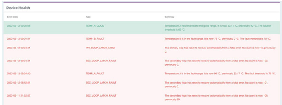
The device health comprises of 3 columns. Event Date is when the device health event was logged. The type is the internal error code that was generated. This is a bit technical so next to it you will also find a Summary column which explains what the issue is and gives some more information about the parameters which triggered it.
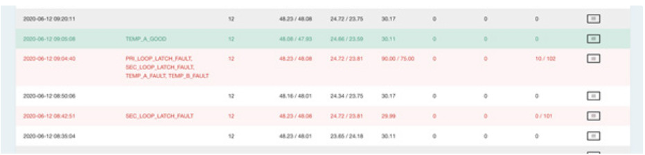
The last table on this page is the Activity Log. The device sends a full diagnostic log to the cloud multiple times per hour. Each logged activity entry for devices can be found here.
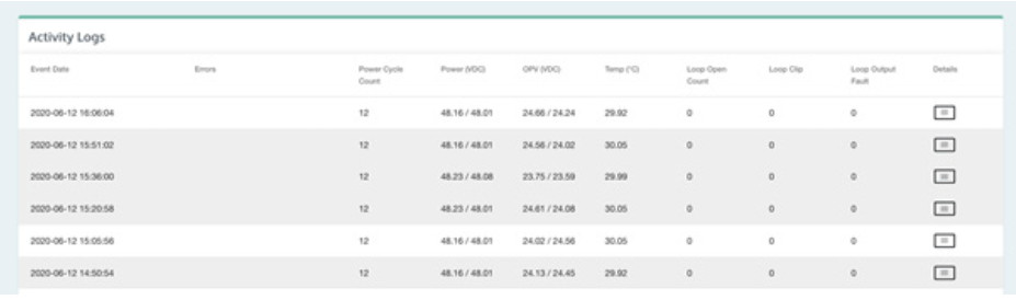
A selection of the most useful fields have been added as columns along the table.
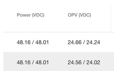
If a column with two values is separated by a slash, this is a phased device. The left is the primary and the right is the secondary values.:
On the right hand side there is a details button:
Because the device logs a large amount of diagnostic data per-event, it would not all fit in on this summary table.
Click this button to see a detailed table of every item which has been submitted:
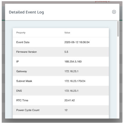
Scroll this window down to see more entries on the table.
Use the X in the top right-hand corner to close this dialogue box or simply click outside of the dialogue box.
If one of these activity log events has report device health issues then the row will be highlighted, and the details will be listed in the error column:
Troubleshooting
| Symptom | Possible Fault | Action |
| Driver does not turn on. | 1) Mains power is absent. 2) Internal issue. |
1) Check mains power. 2) Seek assistance. |
| Interference (buzzing/ whistling/hissing) is heard through induction loop. | 1) Poor input signals. 2) Internal issue. |
1) Power off the hearing loop driver and confirm that interference isn’t from external origin. 2) Disconnect input signals. If sound disappears, check inputs. |
| Driver is excessively hot to touch. | 1) Large amount of mains hum present on input. 2) Internal issue. |
1) Check input signal source. 2) Incorrect hearing loop driver being used. |
| Loop output level indicates current is flowing but I hear nothing in the loop. | 1) Shorted feeder cable. 2) Loop listener is not working or being used too far from loop. |
1) Check feeder cable, although the hearing loop driver will usually refuse to tune to shorted feeder. 2) Check listener and location. |
| Sound is distorted. | 1) Input level has been turned up too high for signal level at input. 2) Input signal is distorted. 3) Output signal is clipping. |
1) Reduce input level setting. 2) Check signal source. 3) Refer to “The Clipping Status Lights are lit” below. |
| Audio from the hearing loop driver is clipping. | The connected hearing loop cable is too long. | 1) Reduce the length of the hearing loop cable. 2) Use a larger diameter cable. 3) Create a two-turn loop. 4) Use a higher voltage driver. |
Please contact your distributor (or Contacte if appropriate) if you are experiencing technical difficulties with the product.
Notification Guide
 Attention
 Phantom Power Inputs A + B are on
 Phantom Power Input A is on
 Phantom Power Input B is on
 Low Cut Filter is on
 Loop is being attenuated
 Signal on
Loop Resistance
Primary loop resistance too high! Check loop and connections Consult user guide Secondary loop resistance too high!
If you encounter the above fault message indicating an issue with the loop, follow the steps outlined below for effective diagnosis and resolution.
Step 1
Reset the mains power. If the error message reappears, proceed to step 2.
Step 2
- Disconnect both the power and the hearing loop(s).
- Use a multi-meter to measure the resistance of the loop.
- Measure the resistance at the NL4 connector, specifically between the conductors used: either 1a – 1b or 2a – 2b.
- Ensure that the resistance readings are below the specified values:
• V22A: Less than 40Ω
• V34: Less than 64Ω
• V34a: Less than 64Ω - If the loop resistance exceeds the aforementioned values but isn’t an open circuit, consider the following possibilities:
a. The loop, including the feeder cable, surpasses the maximum allowable resistance due to excessive length, inadequate gauge size, or a combination of both. Investigate the underlying cause(s) for this.
b. If the reading indicates an open circuit, it’s likely that there’s a physical break in the loop or feeder cable. Investigate and identify the cause of this.
If the loop resistance falls within the specified values (typically less than half these values), the issue could stem from the loop being inadvertently connected to mains or building ground (Earth).
Step 3
- With the mains power disconnected, detach the loop connector.
- Set the multi-meter to Megaohms (MΩ) and measure the resistance of the loop connections and a suitable ground/earth connection. This can include the chassis of an earthed electrical equipment, exposed metal pipes (water or gas), or conduit.
- Ensure that the measured resistance is greater than 10MΩ. Take care not to touch the meter connections while measuring, as this can impact the accuracy of the reading.
4a. If the reading exceeds 10MΩ or the meter indicates an open circuit (O/C) for V22a or V34a, proceed to step 4. For a V34 issue, it’s recommended to seek guidance from your supplier or installer.
4b. If the measured reading is below 10MΩ, there may indicate a serious fault with the loop insulation.. Extremely low readings could indicate a significant fault with the loop insulation.
Before proceeding, address any concerns related to loop insulation.
Step 4
- Set your multi-meter to the Megaohms (MΩ) range. Take care not to touch the meter connections during measurement, as this could influence the reading.
- Measure the resistance between both loops using the multi-meter. The measured resistance should exceed 10MΩ.
- If the measured resistance falls below 10MΩ, investigate the insulation of the loop/feeder cable and inspect the points where the loops come into physical contact with each other.
- If the measured resistance is higher than 10MΩ or the meter shows an open circuit (O/C), it’s recommended to get in touch with your supplier or installer for support.
Technical Specification
V22a:
| Technical Data | ||
| Audio Inputs | 2 X line/microphone inputs (switchable) XLR or Euroblock | Line (optimised for -10dBV to 0dBv) |
| Microphone (12V phantom power via 680W optimised for levels above -45dBv) | ||
| Loop Outputs | Outputs Voltage | 2 x 22.66Vrms (64.09V pk-pk) |
| Output Current | 2 x 8Arms @ 1KHz (22.62A pk-pk) >1200 seconds (20 minutes) | |
| Loop Connector | 2 x NL4 | |
| Audio System | Frequency Response | 100Hz to 5KHz |
| Distortion | THD<1% (-40dB) full current both channels driven | |
| Automatic Gain Control | DSP controlled, peak detecting | |
| High Frequency Compensation | 7 DSP controlled, optimised stages | |
| Audio Signal Delay | 10ms to 40ms | |
| Display | Backlit TFT 480 x 128 pixels (95mm x 25mm) | |
| Control | Single Rotary Push Control | |
| Mains Input | Voltage | 100V-120V /200V-240V AC (universal auto switching with PFC) |
| Frequency | 50Hz/60Hz | |
| Connection | IEC | |
| Cooling | Custom heatsink with temperature-controlled fan | |
V34:
| Technical Data | ||
|
Audio Inputs |
2 X line/microphone inputs (switchable) XLR or Euroblock | Line (optimised for -10dBV to 0dBv) |
| Microphone (12V phantom power via 680W optimised for levels above -45dBv) | ||
| Loop Outputs | Outputs Voltage | 34Vrms (96.1V pk-pk) |
| Output Current | 12Arms @ 1KHz (33.94A) pk-pk >1200 seconds (20 minutes) | |
| Loop Connector | NL4 | |
| Audio System | Frequency Response | 100Hz to 5KHz |
| Distortion | THD<1% (-40dB) full current both channels driven | |
| Automatic Gain Control | DSP controlled, peak detecting | |
| High Frequency Compensation | 7 DSP controlled, optimised stages | |
| Audio Signal Delay | 10ms to 40ms | |
| Display | Backlit TFT 480 x 128 pixels (95mm x 25mm) | |
| Control | Single Rotary Push Control | |
| Mains Input | Voltage | 100V-120V /200V-240V AC (universal auto switching with PFC) |
| Frequency | 50Hz/60Hz | |
| Connection | IEC | |
| Cooling | Custom heatsink with temperature-controlled fan | |
V34a:
| Technical Data | ||
|
Audio Inputs |
2 X line/microphone inputs (switchable) XLR or Euroblock | Line (optimised for -10dBV to 0dBv) |
| Microphone (12V phantom power via 680W optimised for levels above -45dBv) | ||
| Loop Outputs | Outputs Voltage | 2 x 34Vrms (96.1V pk-pk) |
| Output Current | 2 x 12Arms @ 1KHz (33.94A) pk-pk >1200 seconds (20 minutes) | |
| Loop Connector | 2 x NL4 | |
| Audio System | Frequency Response | 100Hz to 5KHz |
| Distortion | THD<1% (-40dB) full current both channels driven | |
| Automatic Gain Control | DSP controlled, peak detecting | |
| High Frequency Compensation | 7 DSP controlled, optimised stages | |
| Audio Signal Delay | 10ms to 40ms | |
| Display | Backlit TFT 480 x 128 pixels (95mm x 25mm) | |
| Control | Single Rotary Push Control | |
| Mains Input | Voltage | 100V-120V /200V-240V AC (universal auto switching with PFC) |
| Frequency | 50Hz/60Hz | |
| Connection | IEC | |
| Cooling | Custom heatsink with temperature-controlled fan | |
Standards
EMC
- BS EN 55103-1: 2009 (EMC emissions)
- BS EN 55103-2: 2009 (EMC immunity)
This product has been designed and tested to comply with the following North American and Canadian standards:
- FCC class “B” EMC (emissions)
- ICES-003
This device complies with Part 15 of the FCC Rules. Operation is subject to the following two conditions: (1) this device may not cause harmful interference, and (2) this device must accept any interference received, including interference that may cause undesired operation.
CAUTION: Changes or modifications not expressly approved by Contacta Systems LTD or an authorised partner could void the user’s authority to operate the equipment.
Correct disposal of this product
This marking indicates that this product should not be disposed with other household waste throughout the EU. To prevent possible harm to the environment or human health from uncontrolled waste disposal and to conserve material resources, this product should be recycled responsibly. To dispose of your product, please use your local return and collection systems or contact the retailer where the product was purchased.
Local dealer:
UK & ROW
+44 (0) 1732 223900
[email protected]
www.contacta.co.uk
US & Canada
+1 616 392 3400
[email protected]
www.contactainc.com