![]() CBU MASTER BUS & CBU REPEATER
CBU MASTER BUS & CBU REPEATER
Device Manual 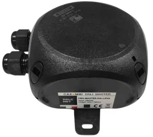
Contents
FEATURES
- CONVERTER+CASAMBI+BUS
- REPEATER CASAMBI
- Input: 230Vac
- Command: APP CASAMBI
- Signal converter from Casaba to DALI o DMX, in MASTER Variant
- Signal repeater, in REPEATER Variant
- Possibility to control DALI or DMX device, by Casaba APP
- Extended temperature range
- 100% Functional test – 5 Years warranty
![]()
PRODUCT CODE
| CODE | Input Voltage | Input Command | Output Command | |
| CBU-MASTER-DALI-IP | 230Vac | APP CASAMBI | DALI (DT6 – DT8) | CONVERTER |
| CBU-MASTER-DMX-IP | 230Vac | APP CASAMBI | DMX | CONVERTER |
| CBU-REPEATER-IP | 230Vac | APP CASAMBI | REPEATER | REPEATER |
➢ PROTECTION
| CBU-MASTER-DALI/DMX | REPEATER | ||
| OVP | Over voltage protection1 | ü | ü |
| IFP | Input fuse protection 1 | ü | ü |
➢ TECHNICAL SPECIFICATION
| CBU MASTER & CBU REPEATER | |
| Nominal Voltage | 230 Vic |
| Voltage Range | 100…240 Vic |
| Mains Frequency | 50/60 Hz |
| Nominal Power @230V2 | 3W max |
| Power loss in standby mode | <500mW |
| Storage Temperature | min: -40 max: +60 °C |
| Ambient Temperature2 | min: -25 max: +60 °C |
| Protection grade | IP66 |
| Mechanical dimensions | 90 x 90 x 65 mm |
| Casing material | Plastic |
| Weight | 88g |
| Only for BUS DALI | |
| I out (only for DALI) | 150mA |
| V out (only for DALI) | 15V |
- Only control logic protection
- Maximum value, dependent on the ventilation conditions.
➢ TECHNICAL NOTE
Installation:
- Isolate the mains supply before the installation or adjusting the switches. Installation and maintenance must be performed in the absence of AC Voltage.
- Installation and maintenance must be performed only by qualified personnel in compliance with current regulations.
- The product must be installed inside an electrical cabinet protected against overvoltage’s.
- The external supply must be protected. The product must be protected from Fuse and/or Circuit Breaker with overcurrent protection correctly dimensioned
- The product must be installed only in a vertical or horizontal position with the cover / label pointing upwards or vertically; No other positions are allowed. Button-up positive is not permitted (downward label).
- The use of the product in harsh environments could limit the output power.
- Keep 230V circuits (LV) and non-SELV circuits separate from safety extra low voltage (SELV) circuits and from all connections of this product. It’s absolutely forbidden to connect for any reason, directly or indirectly, the 230V mains voltage to the bus or to other parts of the SELV circuit.
Command
- The length and type of the connection cables at the BUS (DMX512, DALI or other) must comply with the specification of the respective protocols and regulations and they should be isolated from every wiring or parts at voltage not SELV. It is suggested to use double insulated shielded and twisted cables.
- All the product and the control signal connect at the bus (DMX512, DALI, or other) must be SELV (the devices connected must be SELV or supply a SELV signal)
WARNING: Do not compromise the correct functioning of the device, the product must not be in any way shielded and/or installed inside metal and aluminum boxes.
As any other Casaba product, should not be placed in a metal enclosure or next to large metal structures. Metal will effectively block all radio signals which are crucial to the operation of the product.
MECHANICAL DIMENSIONS

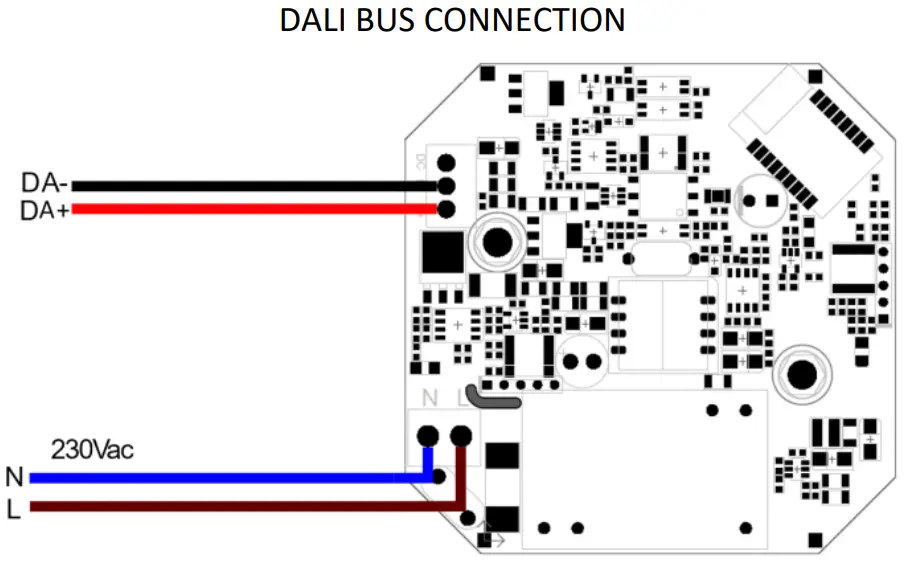
➢ INSTALLATION
Install the product following the below scheme
 |
 |
 |
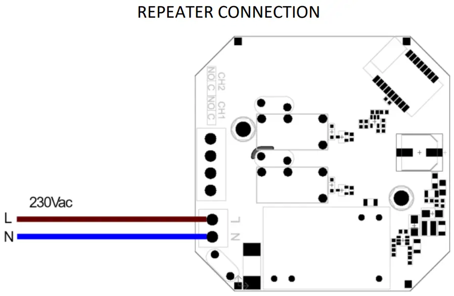
➢ CBU-REPEATER-IP SETUP CASAMBI SIGNAL REPEATER

Characteristics:
The CBU-REPEATER-IP is a Casaba Repeater.
The device receives a Casaba Bluetooth signal and repeats it.
Status Led:
The status of LED is fixed on to indicate the correct power connection to the device.
TYPE OF PROFILE
| Type | # Profile | Name of Profile | Description |
| REPEATER | 9948 | REPEATER | It works as a repeater, forwarding the Casaba signal. |
➢ CBU-MASTER-DALI-IP SETUP CASAMBI SIGNAL CONVERSION INTO DALI PROTOCOL

CHARACTERISTICS:
The CBU-MASTER-DALI-IP is a Casaba to DALI Converter.
The device receives a command signal from Casaba APP and converts the signal into a DALI command. Send DT6 and DT8 command.
See the following table “ADDRESS MAP – DALI” for reference of Casaba-DALI conversion addresses.
STATUS LED:
- When the status of the LED is steady on, the Casaba module is configuring and addressing the SLAVE DALI devices connected to the bus.
- When the LED status flashes quickly, the Casaba module is sending the command set via the Casaba APP to the SLAVE DALI devices connected to the bus.
- When the LED status flashes slowly, it means the DALI bus is shorted.
- When the LED status is off there is no communication in the DALI bus.
AUTOMATIC DETECTION OF SHORT CIRCUITS IN THE DALI BUS:
When the device detects a short circuit on the DALI bus, it automatically switches off the power of bus and the LED signal flashes slowly.
At 15 seconds after the detection of the short circuit, CBU-MASTER-DALI tries to reactivate the power supply of the bus. If the short circuit has been solved, the system returns to work correctly, otherwise the bus remains unpowered and cyclically, every 15 seconds, the device tries again to reactivate the power supply of bus.
NOTE: CBU-MASTER-DALI-IP do not need a DALI Bus power Supply. At switching on, all channels are set at same value 254.
TYPE OF PROFILE
| Type | # Profile | Name of Profile | Description |
| DALI | 9942 (*) | DALI BROADCAST | Basic DALI broadcast dimmer. DALI Dimming Curve: Logarithmic. Set power on level at maximum level (100% – 254). No short addressing required. |
| 13820 | W AUTOMATIC | One channel dimmer: – Dimmer 1: address A0 DALI Dimming Curve: Logarithmic. Set power on level at off (0% – 0). The short address is automatically assigned to the driver, if needed. |
|
| 13818 | WW AUTOMATIC | Two channel dimmers: – Dimmer 1: address A0 – Dimmer 2: address A1 DALI Dimming Curve: Logarithmic. Set power on level at off (0% – 0). The short address is automatically assigned to the driver, if needed. |
|
| 13816 | WWW AUTOMATIC | Three channel dimmers. – Dimmer 1: address A0 – Dimmer 2: address A1 – Dimmer 3: address A2 DALI Dimming Curve: Logarithmic. Set power on level at off (0% – 0). The short address is automatically assigned to the driver, if needed. |
|
| 12992 | WWWW AUTOMATIC | Four channel dimmers. – Dimmer 1: address A0 – Dimmer 2: address A1 – Dimmer 3: address A2 – Dimmer 4: address A3 DALI Dimming Curve: Logarithmic. Set power on level at off (0% – 0). The short address is automatically assigned to the driver, if needed. |
|
| 12993 | TW AUTOMATIC 2700-6000K | Two channel dimmers. – Dimmer 1: address A0-Warm White – Dimmer 2: address A1-Cool White DALI Dimming Curve: Logarithmic. Set power on level at off (0% – 0). The short address is automatically assigned to the driver, if needed. |
|
| 19060 | TW AUTOMATIC 2700-6000K [NEW] | Two channel dimmers. – Dimmer 1: address A0-Warm White – Dimmer 2: address A1-Cool White DALI Dimming Curve: Quadratic. Set power on level at off (0% – 0). The short address is automatically assigned to the driver, if needed. |
|
| 12994 | RGB AUTOMATIC | Three channel dimmers. – Dimmer 1: address A0-Red – Dimmer 2: address A1-Green – Dimmer 3: address A2-Blue DALI Dimming Curve: Logarithmic. Set power on level at off (0% – 0). The short address is automatically assigned to the driver, if needed. |
| DALI | 12995 | RGB+W AUTOMATIC | Four channel dimmers. – Dimmer 1: address AO-Red – Dimmer 2: address Al-Green – Dimmer 3: address A2-Blue – Dimmer 4: address A3-White DALI Dimming Curve: Logarithmic. Set power on level at off (0% -0). The short address is automatically assigned to the driver, if needed. |
|
12996 |
WWWW GROUP |
Four group luminaires. – Dimmer 1: group GO – Dimmer 2: group G1 – Dimmer 3: group G2 – Dimmer4: group G3 DALI Dimming Curve: Logarithmic. Set power on level at off (0% -0). The short address needs to be assigned to the control gear using a DALI Master device. |
|
| 12998 | TW GROUP 2700-6000K |
Two group luminaires. – Dimmer 1: group GO-Warm White – Dimmer 2: group Lg-Cool White DALI Dimming Curve: Logarithmic. Set power on level at off (0% -0). The short address needs to be assigned to the control gear using a DALI Master device. |
|
| 12999 | RGB GROUP | Three group luminaires. – Dimmer 1: group GO-Red – Dimmer 2: group 61-Green – Dimmer 3: group G2-Blue. DALI Dimming Curve: Logarithmic. Set power on level at off (0% -0). The short address needs to be assigned to the control gear using a DALI Master device. |
|
| 13000 | RGB+W GROUP | Four group luminaires. – Dimmer 1: group GO-Red – Dimmer 2:group G1-Green – Dimmer 3:group G2-Blue – Dimmer 4:group G3-White DALI Dimming Curve: Logarithmic. Set power on level at off (0% -0). The short address needs to be assigned to the control gear using a DAU Master device. |
|
| 15539 | 8xW, GROUP SPECIAL | Eight group luminaires. – Dimmer 1: group GO – Dimmer 2: group G1 – Dimmer 3: group G2 – Dimmer4: group G3 – Dimmer 5: group G4 – Dimmer 6: group G5 – Dimmer 7: group G6 – Dimmer 8: group G7 DALI Dimming Curve: Logarithmic. Set Power on Level at 255 (Mask) — Memory Function at Power On. Set System Failure at 255 (Mask) — In case of bus loss, there Isn’t change of LED output. The short address needs to be assigned to the control gear using a DAU Master device. |
| DALI | 24688 | 8xW GROUP | Eight group luminaires. – Dimmer 1: group GO – Dimmer 2: group G1 – Dimmer 3: group G2 – Dimmer 4: group G3 – Dimmer 5: group G4 – Dimmer 6: group G5 – Dimmer 7: group G6 – Dimmer 8: group G7 DALI Dimming Curve: Logarithmic. Set power on level at maximum level (100% – 254). The short address needs to be assigned to the control gear using a DALI Master device. |
| DALI DT8 |
18823 | DALI BC DT8 TW | 1 Address to control 2-channel TW. Send DALI DT8 BROADCAST commands for device that supporting “Colours Temperature Tc”: Dim Level and Colours Temperature channels. DALI Dimming Curve: Logarithmic. |
| Set power on level at maximum level (100%- 254). No short addressing required. | |||
| 21458 | DALI DT8 RGB LINEAR | 1 Address to control 3-channel RGB. Send DALI DT8 commands for device that supporting “RGBWAF colours-type”: Dim and RGBWAF channels. DALI Dimming Curve: Linear. Set power on level at maximum level (100%- 254). The short address is automatically assigned to the driver, if needed. |
|
| 21459 | DALI DT8 RGBW LINEAR | 1 Address to control 4-channel RGBW. Send DALI DT8 commands for device that supporting “RGBWAF colours-type”: Dim and RGBWAF channels. DALI Dimming Curve: Linear. Set power on level at maximum level (100%- 254). The short address is automatically assigned to the driver, if needed. |
|
|
24058
|
DALI DT8 BC RGB LINEAR
|
1 Address to control 3-channel RGB. Send DALI DT8 BROADCAST commands for device that supporting “RGBWAF colour-type”: Dim and RGBWAF channels. DALI Dimming Curve: Linear. Set power on level at maximum level (100%- 254). No short addressing required. |
|
| 24008 | DALI DT8 BC RGB+W LINEAR | 1 Address to control 4-channel RGBW. Send DALI DT8 BROADCAST commands for device that supporting “RGBWAF colour-type”: Dim and RGBWAF channels. DALI Dimming Curve: Linear. Set power on level at maximum level (100%- 254). No short addressing required. |
ADDRESSES MAP – DALI
FIXTURE AUTOMATIC
The Fixture “AUTOMATIC” of the CBU-MASTER-DALI-IP addressing automatically the devices connected to the DALI BUS.
Profile Type: BROADCAST
| Add | Function | Broadcast |
| +ALL | Broadcast | Dimmer (Brightness Value) |
| 0 .. 254 |
Profile Type: W AUTOMATIC – Fixture for only 1 DALI address
| Add | Function | Dimmer |
| A0 | Dimmer 1 | Dimmer (Brightness Value) |
| 0 .. 254 |
Profile Type: WW AUTOMATIC – Fixture for 2 DALI address
| Add | Function | Dimmer |
| A0 | Dimmer 1 | Dimmer (Brightness Value) |
| 0 .. 254 | ||
| A1 | Dimmer 2 | Dimmer (Brightness Value) |
| 0 .. 254 |
Profile Type: WWW AUTOMATIC – Fixture for 3 DALI address
| Add | Function | Dimmer |
| A0 | Dimmer 1 | Dimmer (Brightness Value) |
| 0 .. 254 | ||
| A1 | Dimmer 2 | Dimmer (Brightness Value) |
| 0 .. 254 | ||
| A2 | Dimmer 3 | Dimmer (Brightness Value) |
| 0 .. 254 |
Profile Type: WWWW AUTOMATIC – Fixture for 4 DALI address
| Add | Function | Dimmer |
| A0 | Dimmer 1 | Dimmer (Brightness Value) |
| 0 .. 254 | ||
| A1 | Dimmer 2 | Dimmer (Brightness Value) |
| 0 .. 254 | ||
| A2 | Dimmer 3 | Dimmer (Brightness Value) |
| 0 .. 254 | ||
| A3 | Dimmer 4 | Dimmer (Brightness Value) |
| 0 .. 254 |
Profile Type: TW AUTOMATIC 2700-6000K – TW AUTOMATIC 2700-6000K NEW
| Add | Function | Tunable White |
| A0 | Warm White | Dimmer (Brightness Value) |
| 0 .. 254 | ||
| A1 | Cool White | Dimmer (Brightness Value) |
| 0 .. 254 |
Profile Type: RGB AUTOMATIC
| Add | Function | RGBW |
| A0 | Red | R |
| 0 .. 254 | ||
| A1 | Green | G |
| 0 .. 254 | ||
| A2 | Blue | B |
| 0 .. 254 |
Profile Type: RGB+W AUTOMATIC
| Addr | Function | RGBW |
| A0 | Red | R |
| 0 .. 254 | ||
| A1 | Green | G |
| 0 .. 254 | ||
| A2 | Blue | B |
| 0 .. 254 | ||
| A3 | White | W |
| 0 .. 254 |
FIXTURE GROUP
With “Group” Fixture the CBU-MASTER-DALI-IP sends group commands. The SLAVE devices to be controlled correctly by these Fixture must be previously addressed and assigned to the desired group through a Master DALI.
Profile Type: WWWW GROUP
| Group | Function | Dimmer |
| G0 | Dimmer 1 | Dimmer (Brightness Value) |
| 0 .. 254 | ||
| G1 | Dimmer 2 | Dimmer (Brightness Value) |
| 0 .. 254 | ||
| G2 | Dimmer 3 | Dimmer (Brightness Value) |
| 0 .. 254 | ||
| G3 | Dimmer 4 | Dimmer (Brightness Value) |
| 0 .. 254 |
Profile Type: TW GROUP 2700-6000K
| Group | Function | Tunable white |
| G0 | Warm White | Dimmer (Brightness Value) |
| 0 .. 254 | ||
| G1 | Cool White | Dimmer (Brightness Value) |
| 0 .. 254 |
Profile Type: RGB GROUP
| Group | Function | RGB |
| G0 | Red | R |
| 0 .. 254 | ||
| G1 | Green | G |
| 0 .. 254 | ||
| G2 | Blue | B |
| 0 .. 254 |
Profile Type: RGB+W GROUP
| Group | Function | RGBW |
| G0 | Red | R |
| 0 .. 254 | ||
| G1 | Green | G |
| 0 .. 254 | ||
| G2 | Blue | B |
| 0 .. 254 | ||
| G3 | White | W |
| 0 .. 254 |
Profile Type: 8xW GROUP – 8xW GROUP SPECIAL
| Group | Function | Dimmer |
| G0 | Dimmer 1 | Dimmer (Brightness Value) |
| 0 .. 254 | ||
| G1 | Dimmer 2 | Dimmer (Brightness Value) |
| 0 .. 254 | ||
| G2 | Dimmer 3 | Dimmer (Brightness Value) |
| 0 .. 254 | ||
| G3 | Dimmer 4 | Dimmer (Brightness Value) |
| 0 .. 254 | ||
| G4 | Dimmer 5 | Dimmer (Brightness Value) |
| 0 .. 254 | ||
| G5 | Dimmer 6 | Dimmer (Brightness Value) |
| 0 .. 254 | ||
| G6 | Dimmer 7 | Dimmer (Brightness Value) |
| 0 .. 254 | ||
| G7 | Dimmer 8 | Dimmer (Brightness Value) |
| 0 .. 254 |
The 8xW GROUP SPECIAL profile send SET POWER ON LEVEL and SET SYSTEM FAILURE LEVEL command at 255 (MASK). These commands are sent at the DALI bus when you change the profile, by Casaba APP. For Control Gear to receive these commands correctly, they must be connected to the DALI bus before changing profile.
Profile Type: DALI BROADCAST DT8 TW
| Addr | Function | Broadcast – Colours Temperature Tc – DT8 |
| +ALL | Broadcast TW Colours Temperature Tc | Dimmer (Brightness Value) |
| 0 .. 254 |
Profile Type: DALI DT8 RGB LINEAR
| Add | Function | RGB – DT8 |
| A0 | RGB Colours Type | Dimmer (Brightness Value) |
| 0 .. 254 |
Profile Type: DALI DT8 RGBW LINEAR
| Addr | Function | RGBW – DT8 |
| A0 | RGBW Colours Type | Dimmer (Brightness Value) |
| 0 .. 254 |
Profile Type: DALI DT8 BC RGB LINEAR
| Addr | Function | Broadcast RGB – DT8 |
| +ALL | Broadcast RGB Colours Type | Dimmer (Brightness Value) |
| 0 .. 254 |
Profile Type: DALI DT8 BC RGB+W LINEAR
| Addr | Function | Broadcast RGB+W – DT8 |
| +ALL | Broadcast RGB+W Colours Type | Dimmer (Brightness Value) |
| 0 .. 254 |
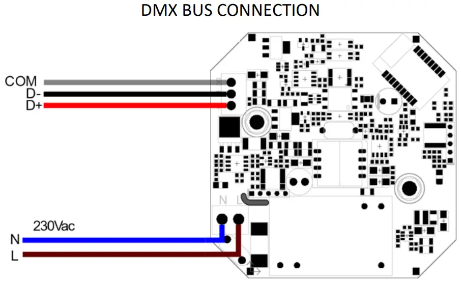
➢ CBU-MASTER-DMX-IP SETUP CASAMBI SIGNAL CONVERSION INTO DMX PROTOCOL 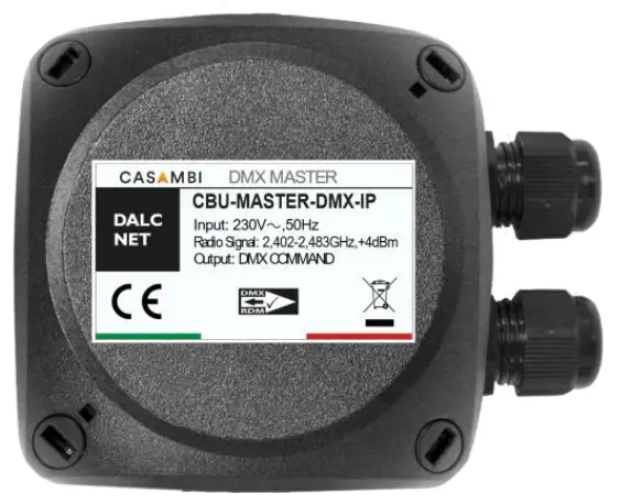
Characteristics:
The CBU-MASTER-DMX-IP is a Casaba to DMX Converter.
The device receives the command signal from Casaba APP and convert it into a DMX command.
See the following “CHANNELS MAP – DMX” table for the reference of the Casaba-DMX conversion addresses.
Status Led:
Status LED is fixed on when the Casaba command is right transmitted.
Status LED slowly flashes (1 flash per second), when the device is powered.
TYPE OF PROFILE
| typo | # Profile | Name of Noble | Description |
| DMX | 13808 | W | One channel dimmer: – Dimmer 1: channel 1 |
| 13807 | WWWW | Four channel dimmers. – Dimmer 1: channel 1 – Dimmer 2: channel 2 – Dimmer 3: channel 3 – Dimmer 4: channel 4 |
|
| 13809 | TW | Two channel dimmers. – Warm White Dimmer: channel 1 – Cool White Dimmer: channel 2 |
|
| 13810 | RGB | Three channel dimmers. – Red Dimmer channel 1 – Green Dimmer channel 2 – Blue Dimmer: channel 3 |
|
| 13811 | RGB+W | Four channel dimmers. – Red Dimmer channel 1 – Green Dimmer: channel 2 – Blue Dimmer: channel 3 – White Dimmer: channel 4 |
|
| 13812 | MRGB+S | Five channel dimmers. – Master Dimmer channel – Red Dimmer channel 2 – Green Dimmer channel 3 – Blue Dimmer: channel 4 – Strobe Rate Channel: channel 5 |
|
| 13813 | MRGBW+S | Six channel dimmers. – Master Dimmer channel – Red Dimmer channel 2 – Green Dimmer: channel 3 – Blue Dimmer: channel 4 – White Dimmer: channel 5 -Strobe Rate Channel: channel 6 |
CHANNEL MAP – DMX
Profile Type: W – 1 DMX channel
| Ch. | Function | Dimmer |
| 1 | Dimmer 1 | Dimmer (Brightness Value)
0 .. 255 |
Profile Type: WWWW – 4 DMX channel
| Ch. | Function | Dimmer |
| 1 | Dimmer 1 | Dimmer (Brightness Value)
0 .. 255 |
| 2 | Dimmer 2 | Dimmer (Brightness Value) 0 .. 255 |
| 3 | Dimmer 3 | Dimmer (Brightness Value) 0 .. 255 |
| 4 | Dimmer 4 | Dimmer (Brightness Value) 0 .. 255 |
Profile Type: TW
| Ch. | Function | Tunable White |
| 1 | Warm White | Dimmer (Brightness Value) 0 .. 255 |
| 2 | Cool White | Dimmer (Brightness Value) 0 .. 255 |
Profile Type: RGB
| Ch. | Function | RGB |
| 1 | Red | R 0 .. 255 |
| 2 | Green | G 0 .. 255 |
| 3 | Blue | B 0 .. 255 |
Profile Type: MRGBS
| Ch. | Function | Master+RGB+Strobe |
| 1 | Master Dimmer | Master Dimmer (Brightness Value) 0 .. 255 |
| 2 | Red | R 0 .. 255 |
| 3 | Green | G 0 .. 255 |
| 4 | Blue | B 0 .. 255 |
| 5 | Strobe Rate (*) | STROBO 0 .. 255 |
Profile Type: RGBW
| Ch. | Function | RGBW |
| 1 | Red | R 0 .. 255 |
| 2 | Green | G 0 .. 255 |
| 3 | Blue | B 0 .. 255 |
| 4 | White | W 0 .. 255 |
Profile Type: MRGBWS
| Ch. | Function | Master+RGB+Strobe |
| 1 | Master Dimmer | Master Dimmer (Brightness Value) 0 .. 255 |
| 2 | Red | R 0 .. 255 |
| 3 | Green | G 0 .. 255 |
| 4 | Blue | B 0 .. 255 |
| 5 | White | W 0 .. 255 |
| 6 | Strobe Rate (*) | STROBO 0 .. 255 |
(*) Strobe Rate execute the functions of the strobe address of the control unit connected to the CBU-MASTER-DMX-IP. For example, if you connect the CBU-MASTER-DMX-IP to the DLD1248-4CV-DMX control unit, which is also set with the MRGB+ or MRGBW+ map, the Strobe Rate address has the following characteristics:
| 6 | Strobe Rate | fix 0..15 | blackout 16..31 | 1fps
32..47 |
2fps
48..63 |
3fps
64..79 |
4fps
80..95 |
5fps
96..111 |
6fps
112..127 |
7fps
128..143 |
8fps
144..159 |
9fps
160..175 |
10fps
176..191 |
12fps
192..207 |
14fps
208..223 |
16fps
224..239 |
fix 240..254 |
For other devices check the behavior of the device at the respective channel 6 of the DMX.
➢ BLUETOOTH RANGE
The range depends a lot on the surroundings and materials or building obstacles, see the technical notes on page 3.
![]() DALCNET Seral, Registered office: Via Lago di Garda, 22 – 36077 Alta villa Vicentine (VI) – Italy
DALCNET Seral, Registered office: Via Lago di Garda, 22 – 36077 Alta villa Vicentine (VI) – Italy
Headquarters: Via Lago di Garda, 22 – 36077 Alta villa Vicentine (VI) – Italy
VAT: IT04023100235 – Tel. +39 0444 1836680 – www.dalcnet.com – [email protected]