![]()
INSTALLATION INSTRUCTIONS SERIES 600
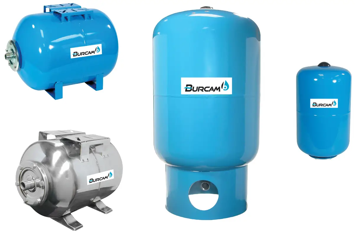
PRESSURE TANKS
Contents
600 Series 2.1 Gal Inline Pressure Tanks
Steel and Stainless Steel Please read these instructions carefully.
Failure to comply to instructions and designed operation of this system, may void the warranty.
This product has been carefully packaged at the factory to prevent damage during shipping. However, occasional damage may occur due to rough handling. Carefully inspect your pressure tank for damages that could cause failures. Report any damage to your carrier or your point of purchase.
© 2023 BURCAM Printed in Canada 600576
Application
Designed to be installed with deep well pumps, shallow well jet pumps and convertible jet pumps.
Maximum operating pressure 75 PSI.
Features
No water to metal contact.
Synthetic butyl bladder.
No need for air volume control.
Made from treated steel or stainless steel.
Replaceable bladder.
MATERIAL REQUIRED
‘‘In-line’’ models
1’’ X 3’’ galvanized nipple.
1’’ X 1’’ X 1’’ galvanized T or cross T.
Check your pump’s discharge opening (if necessary, use a reducing bushing to 3/4’’ NPT size).
‘‘Free standing’’ models
One 1’’ or 1 1/4’’ galvanized elbow (90°) as required.
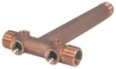
One 1’’ long brass tank T (650651 or 650662) or tank tee kit (650665 or 650666).
One service line gate valve.
One 1-1/4’’ to 1’’ galvanized reducing adaptor if required.
One 1/4’’ X 3’’ galvanized nipple.
Others accessories
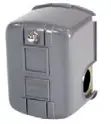
Pressure switch.
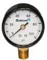
Pressure gauge.
Check pipe size to make sure it is same size as the adaptors.
1 teflon tape.
Miscellaneous: 1/4’’ and 1/2’’ plugs for T, adaptors for T. (Both sides of tank if desired)
* ( Optional: relief valve, bib drain faucet to drain tank).
Other accessories are available from your BURCAM authorized dealer.
 |
 |
 |
 |
 |
 |
| PRESSURE GAUGE | LOW PRESSURE CUT-OFF SWITCH |
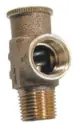
DRAIN VALVE | PRESSURE RELIEF VALVE | BRONZE ADAPTORS | BRASS TANK T |
| 750768 1/8’’ 750769 1/4’’ |
150159S 20/40 150147S 30/50 |
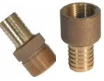
650659 | 150162 | 750949 1’’ Female 750870 3/4’’ Male |
650651 Long 650652 Short 650662 Long |
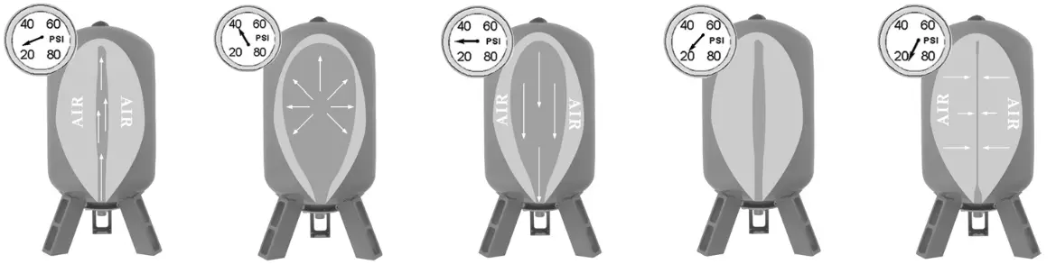
Pre – Charging tank:
Captive air pressure tanks for water storage are charged with air at the factory. As the tank begins to deliver water into the home’s plumbing system, the compressed air in the tank pushes the water out of the bladder. When the pump’s pressure switch cut-in setting is reached, the pump will start to deliver water to plumbing lines and begin to store water in the tank’s bladder.
As the water enters in the tank’s bladder, the captive air above the bladder, in the tank, is compressed and the water pressure increases until the pump’s pressure switch cut-off setting is reached and the pump will stop pumping.
Pre – Charging tank: (Adjustment of the pressure must be done when the tank is empty of water).
For pump systems, operating with the pressure switch setting 20 PSI (cut-in) 40 PSI (cut-out), tank pressure should be adjusted to 18 PSI.
(Check with tire gauge)
For pump systems, operating with the pressure switch setting 30 PSI (cut-in) 50 PSI (cut-out), tank pressure should be adjusted to 28 PSI. (Check with tire gauge)
 |
||||
| STEP ONE Pump pushes water inside bladder against the air pressure in the tank. |
STEP TWO Pressure switch determines when full of water. |
STEP THREE On demand, water goes into discharge pipe. |
STEP FOUR The air pressure pushes water out of the tank as water is used. |
LAST STEP The pump starts when the tank is empty. |
ELECTRICAL INSTALLATION
We recommend that a licensed electrician be employed to do wiring to the pressure switch. Permanently ground the motor in accordance to the electrical codes for your area. Do not use an extension cord to connect your pump to the power source. From your distribution panel to the pressure switch, we recommend a wire gauge not smaller than 14 gauge, and an adequate gauge for a submersible pump.
Pressure switch setting (start/stop 20/40 or 30/50) has been made in factory.
An adjustment may be done to give other operating pressures.Adjustment ormodification of start/stop setting of pressure switch have to be done carefully.
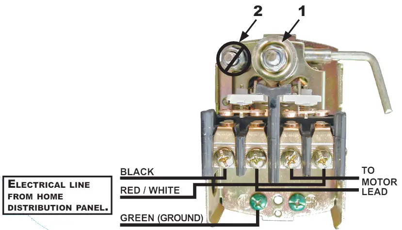
Turn adjustment nut 1 clockwise half turn at a time to raise start and stop pressure setting. Never turn nut 2. This will change the 20 PSI range between start and stop pressure and may damage your tank’s bladder or modify the efficiency of your water system. Check system operation after each adjustment.
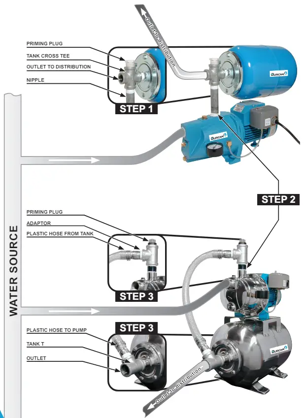
INSTALLATION INSTRUCTIONS IN-LINE MODELS
(see on next page)
STEP 1 Install your pump in the desired location, leaving ample room to mount your tank to the pump’s discharge connection.
STEP 2 Check your pump’s discharge connection, common size for many pumps is 1” NPT. Verify the tank connector (3/4’’ or 1’’) and use the appropriate fittings using teflon tape on the threads.
Into the pump’s discharge connection (or bushing) install a 3” galvanized nipple, using teflon tape on the threads. Tighten into opening with your pipe wrench.
STEP 3 Into the nipple, (see diagram) install a 1’’ X 1’’ X 1’’ galvanized T.
Tighten with your pipe wrench.
STEP 4 “In-line” tanks may be installed vertically or horizontally.
Vertical installation: screw the tank into the top opening of the tee, using an ample supply of teflon tape on the threads. Twist the tank into the elbow until it becomes very tight to turn.
Horizontal installation (tank in position over pump’s motor) : install a galvanized elbow into the top of the T, then screw the tank into the opening of the elbow using an ample supply of teflon tape on the threads. Twist the tank into the elbow until it becomes very tight to turn. Some pumps may have a higher pump body than others, if so, change the length of your 3” nipple to clear the top of the pump’s water body.
From the “free opening” in the galvanized T, run your service line to your home’s plumbing system using a service gate valve.
TYPICAL TANK INSTALLATION IN-LINE AND HORIZONTAL POSITION
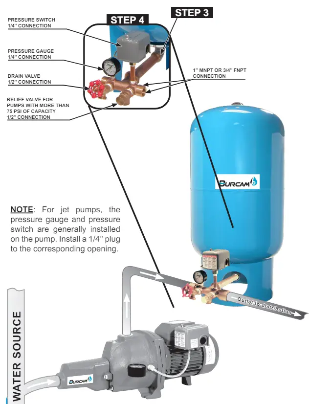
INSTALLATION INSTRUCTIONS FREE-STANDING MODELS
(see on next page)
STEP 1 “Free-Standing” type tanks have to be installed offset from your pump, and in “the line” coming from your pump’s discharge connection (either a jet or submersible pump). Turn your tank on its side and install a galvanized 90º elbow (1” or 1 1/4” as needed) to the inlet-outlet connection, using an ample supply of teflon tape on the threads.
STEP 2 Determine the position or location in which you wish to leave your tank permanently. Leave ample room to make your tank connections.
STEP 3 Screw the long end of the tank T (650651) to the tank elbow’s using teflon tape. If required, install a reducing adaptor 1 1/4” – 1” NPT.
STEP 4 For a submersible pump, install a pressure gauge (750769) and a pressure switch (150147S) (with a 1/4” X 3” nipple) in the 1/4” opening of the tank T. Then, install a drain valve (650659) and a safety relief valve (150162) in the 1/2” opening of the tank T. (see page 7)
STEP 5 For a jet pump, install a 1/4” plug in each 1/4” opening of the tank T. In a 1/2” opening, install a drain valve (650659). In the last opening, install a safety relief valve (150162), if your maximum pump pressure is over 75 PSI. If not, install a 1/2” plug in this opening.
In the service line leading from the tank T, we recommend that you install a service gate valve to allow you to shut-off your water supply in the case of repairs to the home’s water fixtures.
NOTES
The above parts are recommended. Use teflon tape on all threads.
Use a pipe wrench to tighten each piece adequately.
The tank size is very important. Ensure that you select a tank which will meet your requirements. Several tank models are available (larger or smaller).
TYPICAL TANK INSTALLATION UPRIGHT POSITION
REPLACEMENT PARTS
| Tank Model | Style | Material | Volume (L) | Volume (US Gal) | Bladder, |
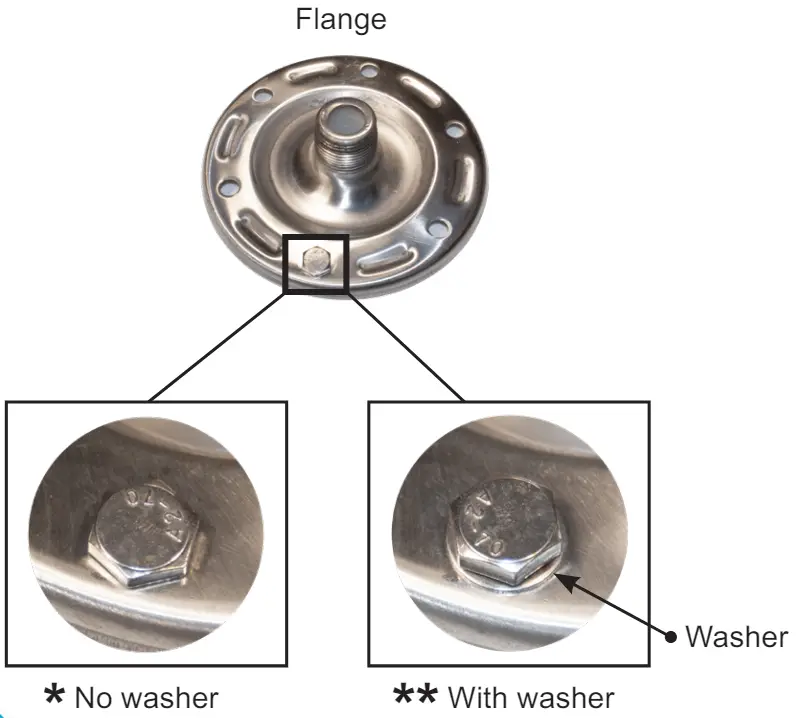
Flange  |
Flange description (Inlet connection & diameter) |
| 600541B | in line | steel with blue epoxy-baked finish | 8 | 2 | 6005016 | 6005136 | 1″ NPT (6 HOLES, 4 3/8″) |
| 600542B | in line | steel with blue epoxy-baked finish | 20 | 5 | 6005026 | 6005176 | 1″ NPT (6 HOLES, 6″) |
| 600543B | in line | steel with blue epoxy-baked finish | 35 | 9 | 6005036 | 600517B | 1″ NPT (6 HOLES, 6″) |
| 600544B | vertical | steel with blue epoxy-baked finish | 60 | 16 | 6005056 | 600517B | 1″ NPT (6 HOLES, 6″) |
| 600545B | vertical | steel with blue epoxy-baked finish | 80 | 21 | 6005196 | 6005176 | 1″ NPT (6 HOLES, 6″) |
| 6005468 | vertical | steel with blue epoxy-baked finish | 100 | 26 | 6005196 | 6005176 | 1″ NPT (6 HOLES, 6″) |
| 600547B | vertical | steel with blue epoxy-baked finish | 150 | 40 | 6005246 | 6005176 | 1″ NPT (6 HOLES, 6″) |
| 600614B | horizontal | steel with blue epoxy-baked finish | 80 | 21 | 6005196 | 6005176 | 1″ NPT (6 HOLES, 6″) |
| 600650B | horizontal | steel with blue epoxy-baked finish | 25 | 7 | 6005096 | 600517B | 1″ NPT (6 HOLES, 6″) |
| 60065033(“) | horizontal | stainless steel | 25 | 7 | 600509Z | 600517Z | 1″ NPT (6 HOLES, 6″) |
| 60065033(‘) | horizontal | stainless steel | 25 | 7 | 6005096 | 600517B | 1″ NPT (6 HOLES, 6″) |
| 600652B | horizontal | steel with blue epoxy-baked finish | 60 | 16 | 6005056 | 6005176 | 1″ NPT (6 HOLES, 6″) |
| 60065253(“) | horizontal | stainless steel | 60 | 16 | 600505Z | 600517Z | 1″ NPT (6 HOLES. 6″) |
| 60065253(‘) | horizontal | stainless steel | 60 | 16 | 6005056 | 6005176 | 1″ NPT (6 HOLES. 6″) |
![]()
2190 Dagenais Blvd. West
Laval (Quebec)
Canada
H7L 5X9
Tel. : 514.337.4415
Fax : 514.337.4029
[email protected]
see us at www.burcam.com