BuoQua 15.7 x 20 x 30.6 Inch Stainless Steel BBQ Island Drawer Storage

Contents
PRODUCT INTRODUCTIONS
Air curtains can effectively block the convection of indoor and outdoor air. They can reduce penetration outside dust, insects, unconditionedair to improve indoor air quality and maintain indoor temperature. Air curtains can be commercial and is widely used in shopping malls, supermarkets, theaters, restaurants, warehouses, shops, bakeries, kitchens, home living rooms, etc.
INSTALLATION PLANNING & CAUTIONS
- Please install the unit in the sturdy wall to ensure safety.
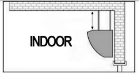
- Please install the unit inside the room.
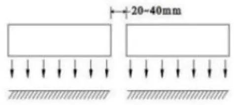
- Use more than one unit of air curtain to fill up the width of the doorway, please provide 20-40 mm gaps between the units.
- DO NOT expose to water or rain, which will increase the risk of electric shock.

- DO NOT use the unit where there is a risk of fire or an explosion.

- Unauthorized modification may impair the function or affect the life of the product.

MOUNTING INSTRUCTIONS
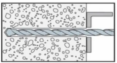
A. Installation on the concrete wall:
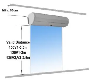
Step 1: Please ensure that the machine is at least 10 cm from the roof.
Step 2: Unpack the machine and check any damage.
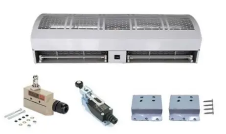
TZ-6003 TZ-8108 Brackets
Step 3: Unscrew the fixing screws and take off the mounting plate on the back of the air curtain.

Step 4: Determine the installation position with the mounting plate. Secure the expansion bolts in place.

Step 5: Tighten the nuts to secure the mounting plate to the wall after cement setting.

Step 6: Hang up the main body on to the installation plate, and then tighten the bottom fixing screws.

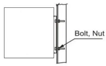
B. Other installation methods
Installation on the wooden wall
Refer to Step 3 and determine the installation position with the mounting plate. Secure the wood screws in place.

Installation on the steel framework
Refer to Step 3 and determine the installation position with the mounting plate. Secure the bolts in place.
OPERATING INSTRUCTIONS
- Connect power to the unit.
- Press the switch on the unit, to set speed to OFF, LOW and High.
- Adjust air guide louvers to preferred positions.
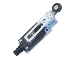
LIMIT SWITCHES
Each air curtain is equipped with two types of limit switches, TZ-6003and TZ8108, allowing the air curtain to run at selected speed when the door is open and be inactive when the door is closed.
DETAILS FOR LIMIT SWITCHES
| TZ-6003 | TZ-8108 | |
 |
 |
|
| Operating force(Max.) | 250~350g | 750g |
| Release force(Min.) | 114g | 100g |
| Pre-travel(Max.) | 0.5mm | 20° |
| Over travel(Max.) | 0.05mm | 50° |
| Movement differential(Min.) | 3.6mm | 12° |
CONNECTION DIAGRAM
TZ-6003

TZ-8108
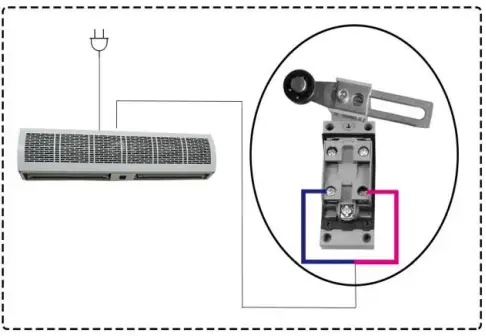
Note: We have connected TZ-6003 to each air curtain for curtomers. Customers can choose the type of switch according to the actual situation of the door. If the customer needs to use TZ-8108, cut theTZ-6003 off and then connect the wires to the TZ-8108.
The following is the recommended installation method according to the type of door
| Door Type | Installation Diagram | Switch Models | Installation Method |
| Wide door frame | 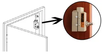 |
TZ-6003 TZ-8108 | Mount the limit switch on the side of the door frame. |
| Narrow door frame | 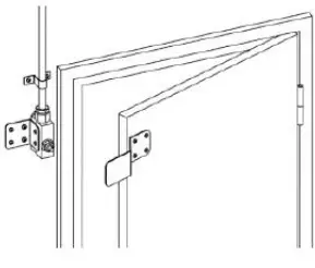 |
TZ-6003 | Step 1: Mount the limit switch on the wall beside the door frame. Step 2: Use the brackets (included) to assist in opening the switch. |
| Double Sliding Door |  |
TZ-6003 TZ-8108 | Step 1: Mount the limit switch on the wall beside the door frame.
Step 2: Mount the brackets (Included) on the door frame. |
CONNECTION DIAGRAM
Two-speed model

Three-speed model

MAINTENANCE AND CLEANING
- Disconnect the power source before maintenance service.
- Routine maintenance must be done every year.
- Use a clean lacquer brush to remove dust on the fans and the electric motor.
- The surfaces should be wiped with a detergent, and xylene, thinners, alcohol or any other such chemicals is not allowed.
- If any part of the unit is damaged, please don’t
TECHNICAL PARAMETERS
U.S.A
|
Model |
Voltage (V) | Frequency (Hz) |
High speed |
Medium speed |
Low speed |
||||||
| CFM (ft3/min) | FPM (ft/min) | Input Power (W) | CFM
(ft3/mn) |
FPM (ft/min) | Input Power
(W) |
CFM
(ft3/min) |
FPM
(ft/min) |
Input Power
(W) |
|||
| 1506001V1 | 110 | 60 | 1007 | 2165 | 300 | – | – | – | 830 | 1968 | 245 |
| 1509001V1 | 110 | 60 | 1511 | 2165 | 329 | – | – | – | 1372 | 1968 | 247 |
| 15010001V1 | 110 | 60 | 1666 | 2165 | 353 | – | – | – | 1490 | 1968 | 260 |
| 15012001V1 | 110 | 60 | 2014 | 2165 | 447 | – | – | – | 1831 | 1968 | 341 |
| 15015001V1 | 110 | 60 | 2515 | 2165 | 666 | – | – | – | 2285 | 1968 | 508 |
| 1209001V1 | 110 | 60 | 667 | 2952 | 378 | – | – | – | 577 | 2559 | 337 |
| 12010001V1 | 110 | 60 | 730 | 2952 | 390 | – | – | – | 612 | 2559 | 330 |
| 12012001V1 | 110 | 60 | 890 | 2952 | 504 | – | – | – | 771 | 2559 | 434 |
| 12015001V1 | 110 | 60 | 1113 | 2952 | 577 | – | – | – | 964 | 2559 | 508 |
Europe/ Australia
|
Model |
Voltage (V) | Frequency (Hz) |
High speed |
Medium speed |
High speed |
||||||
| CFM
(ft3/min) |
FPM
(ft/min) |
Input Power (W) | CFM (ft3/min) | FPM (ft/min) | Input Power (W) | CFM
(ft3/min) |
FPM (ft/min) | Input Power
(W) |
|||
| 1256001V2 | 220 | 50 | 880 | 2165 | 150 | – | – | – | 736 | 1771 | 123 |
| 1259001V2 | 220 | 50 | 1322 | 2165 | 186 | – | – | – | 1081 | 1771 | 154 |
| 12510001V2 | 220 | 50 | 1351 | 2165 | 270 | – | – | – | 1199 | 1771 | 210 |
| 12512001V2 | 220 | 50 | 2204 | 2165 | 325 | – | – | – | 1443 | 1771 | 268 |
| 12515001V2 | 220 | 50 | 2644 | 2165 | 470 | – | – | – | 1803 | 1771 | 410 |
| 1259001V3 | 220-240 | 50 | 1322 | 2165 | 186 | – | – | – | 1081 | 1771 | 154 |
| 125900-3-1V3 | 220-240 | 50 | 1351 | 2165 | 186 | 1187 | 1968 | 178 | 1081 | 1771 | 154 |
| 1251200-3-1V3 | 220-240 | 50 | 2204 | 2165 | 325 | 1632 | 1968 | 270 | 1443 | 1771 | 268 |
| 1251500-3-1V3 | 220-240 | 50 | 2644 | 2165 | 370 | 2077 | 1968 | 352 | 1803 | 1771 | 310 |