![]()
![]() LDS Bus EC Sensor USB Adapter
LDS Bus EC Sensor USB Adapter
User Guide
Setup Instructions:
The LDS Bus USB Adapter serves two functions: 1) Configure LDS Bus Devices; 2) Create an LDS Bus
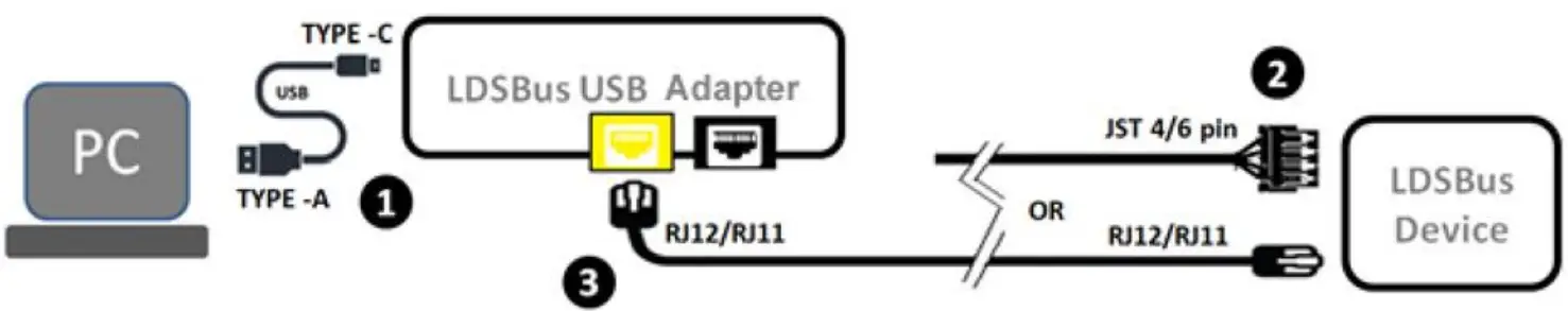
To Configure LDS Bus Device (Sensors/Actuators)
Step 1:
Connect the LDSBus USB Adapter to a PC with a USB-C to USB-A (or USB-C to USB-C) cable.
Step 2:
Ensure that the LDSBus Device is connected to its cable at one end.
Step 3:
Attach the other end of the cable to the LDSBus USB Adapter as shown.
Step 4:
Scan the QR code or visit the link provided below to download the LDSBus Configuration Utility and obtain step by step instructions for configuration.
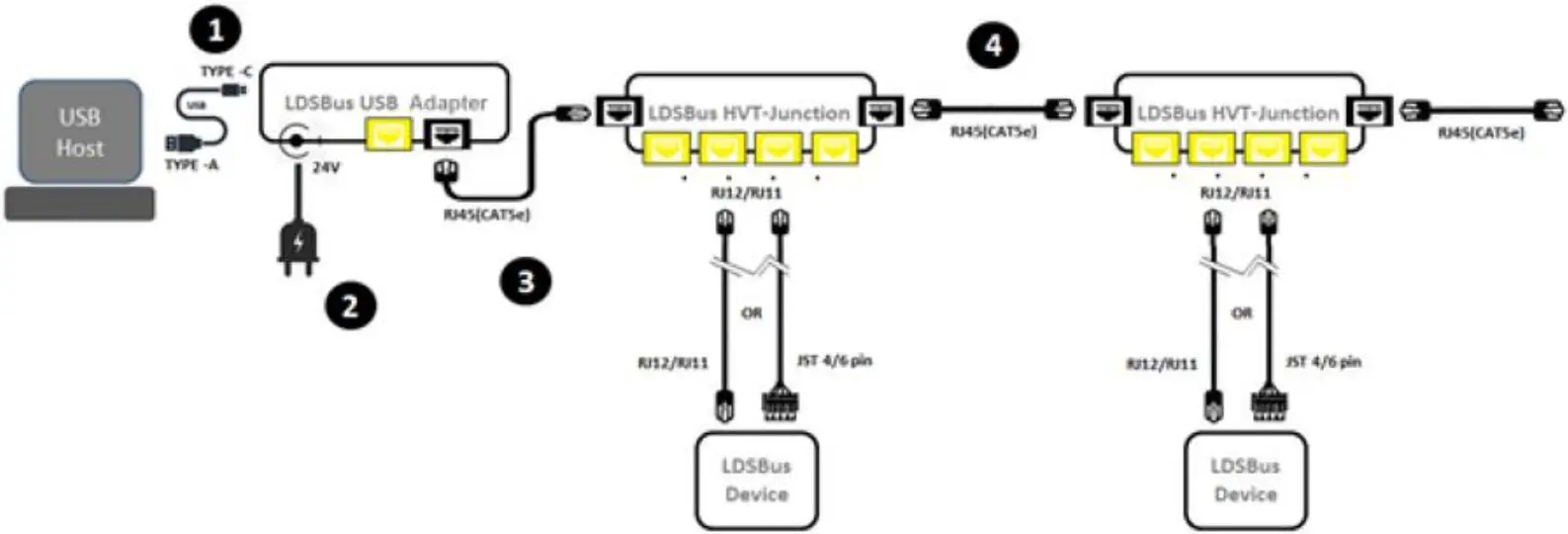
 2) To Create an LDSBus
Step 1:
Connect the LDS Bus USB Adapter to a USB Host.
(Windows/Linux PC, RPi3/4, or other supported hosts)
Step 2:
Connect a 24VDC/18W power adapter to the DC jack and power on. (Power to the LDSBus will be enabled by software)
Step 3:
Connect the first LDSBus HVT-Junction to the LDSBus USB Adapter using a RJ45 (CAT5e) Cable.
Step 4:
If there is more than one LDSBus HVT Junction, chain them together as shown.
Step 5:
Scan the QR code or visit the link provided below to download software to operate the bus.
Note: Enable termination for last LDSBus Device in the bus using the LDSBus Configuration Utility
Please scan QR code A or visit https://brtsys.com/warranty for warranty registration using the UUID and Product Key Sticker Area

View the full information of the LDSBus USB Adapter, application setup and installation at https://brtsys.com/resources/ or scan QR Code B.
