Contents
BLUE JAY BJ195-X Series DC Panel Meter

Product Information
The BJ195PUI DC Panel Meter is a digital meter used for power quality monitoring, factory automation, and building automation. Itcan measure various power parameters in the power grid such as current, voltage, RMS power load, and energy consumption. This meter can replace traditional analog measurement instruments, improving system accuracy and reliability.
Applications:
- Measure all power parameters
- Monitor and control energy measurement and electrical fire
- Replace three-phase power meters and three-phase electricity transmitters
- Detect transformers, generators, capacitors, and electric motors
- Used in medium and low-pressure systems
- Integrates with SCADA, EMS, and DCS systems
Product Usage Instructions
- Before turning on the power supply, ensure that the power supply is within the instrument’s specifications.
- During installation, ensure that the current input terminal is non-open and the voltage input terminals are non-shortcircuit.
- Do not impose high pressure on the communication terminal (RS485 or Ethernet).
- Make sure the instrument wiring is consistent with the internal system settings.
- When communicating with a PC, ensure that the instrument communication parameters are consistent with the PC.
Read me
When you use BJ195-X Series Digital Meter, be sure to carefully read this user manual, and be able to fully understand the implications, the correct guidance of operations in accordance with user manual, which will help you make better use BJ193 series Digital Meter, and help to solve the various problems at the scene.
- Before the meter turning on the power supply, be sure that the power supply within the provisions of the instrument;
- When installation, the current input terminal must non-open, voltage input terminals must Non-short circuit;
- Communication terminal (RS485 or Ethernet) is strictly prohibited to impose high pressure;
- Be sure the instrument wiring consistent with the internal system settings;
- When communicating with the PC, instrument communication parameters must be consistent with the PC.
- Please read carefully before using this user manual
- Please save this document
SUMMARIZE
BJ195-X Series Digital Meter is used for power quality monitoring, factory automation and building automation.
These series can measure the power parameters in power grid:
Current, Voltage, RMS power load, Energy consumption.
It can replace many of a traditional analog measurement instruments, improve system accuracy and reliability.
APPLICATIONS
- Measure all power parameters;
- Monitor and control, energy measurement and electrical fire;
- Replace the three-phase power meter, three phase electricity transmitter;
- Transformers, generators, capacitors and electric motors distributed detection;
- Medium and low pressure systems;
- SCADA, EMS, DCS integrators.
SPECIFICATIONS
- Reference standard
- Basic electricity
GB/T13850-1998 (IEC688-1992) - Active power
GB/T17215-2002 (IEC61036:2000) - Reactive power
GB/T17882-1999 (IEC61268:1995)
- Basic electricity
- Accuracy standards
- Parameter Accuracy
- Voltage 0.2 %fs
- Current 0.2%fs (depends on Shunt)
- Power 0.5%fs
- Energy 1.0%fs
- Input
- Voltage: Rated 300/ 600/ 1000V
- Current: Rated 75mVA (optional 50mV / 100mV or customized)
- Load
- Voltage: <0.5VA / phase (rated 300V)
- Current: <0.5VA / phase (rated 5A)
- Overload
- Current: 1.2 times rated continuous; 10 seconds for 10 times the rated.
- Voltage: 1.2 times the rated continuous; 10 seconds for 2 times.
- Dielectric strength
- IEC 688 / IEC 255-3 (1989)
- 2kV AC RMS 1 minute, between input / output / case / power supply.
- EMC Test
Standard Test voltage Electrostatic discharge immunity test:
IEC-61000-4-2 level 4
8Kv
Electrical fast transient burst immunity test IEC61000-4-4 level 3 Input 1kV; Power supply 2kV
Surge (Shock) immunity test
IEC61000-4-5 level 4
common mode test voltage 4kV - Work environment
- Temperature: -20℃℃~ +60
- Humidity: RH No condensation
- Protection
- Panel: IP40
- Storage conditions
- Temperature::-25℃℃~+70
- Humidity: RH 95%
- Power supply
- AC /DC 85-265V
- Maximum power consumption 3W
INSTALLATION AND START-UP
The manual you hold in your hands contains information and warnings that the user should respect in order to guarantee a proper operation of all the instrument functions and keep its safety conditions. The instrument must not be powered and used until its definitive assembly on the cabinet’s door.
Whether the instrument is not used as manufacturer’s specifications, the protection of the instrument can be damaged.
When any protection failure is suspected to exist (for example, it presents external visible damages), the instrument must be immediately powered off. In this case contact a qualified service representative.
Installation
Mounting
Instrument is to be mounted on panel. All connections keep inside the cabinet.
Note that with the instrument powered on, the terminals could be dangerous to touching and cover opening actions or elements removal may allow accessing dangerous parts.
Therefore, the instrument must not be used until this is completely installed.
Notes:
Input signal: BJ195-X Series using a separate acquisition calculate for each measurement channel, to ensure consistent in use, for different load forms, it’s a variety of connection mode. Access wire shall be met 2.5 square mm.
- A. Voltage input
Input voltage should not exceed the rated input voltage products 450V, Otherwise, you should use external VT. Suggest 1A fuse be installed in the voltage input side. - B. Current Input
Standard input current is 5A or 1A, if greater than 5A/1A should use external CT.
When the CT is connected with other meters, make sure wiring methods be used in series.
Warming: Forbid to install a CT on the live feeder wire with open secondary leads. This can be extremely dangerous!
Before remove the current input connection, must be sure to disconnect the primary circuit or shorted secondary circuit of CT. - C. Sequence of wire
Warming: Please make sure that the input voltage and current corresponding to the same phase, sequence, and the same direction; Otherwise, the Values and symbols will be wrong! (Power and Energy)
Always observe the physical orientation of CT (P1 – P2) when installing on the feeder wire. Always pay attention to wiring polarity and phasing when terminating the CT leads to the BJ195-X Series. S1 connect to Ix*, S2 connect to Ix.
The input network configuration of instrument depends on the CT number of the system: in the condition of 2 CT, select the three-phase, three-lines two components; in the condition of 3 CT, select the three-phase, four-lines three component mode.
Instrument connection mode, set of the instrument (programming input network NET) should be the same load wiring as measured wiring. Otherwise, the measurement instrument will lead to incorrect voltage or power.
In three-phase 3 wire mode, measurement and shows the line voltage;
In three-phase 4 wire mode, measurement and shows phase voltage and line voltage both. - D. Auxiliary power
BJ195-X Series with universal (AC / DC) power input, if not for a special statement, we provide the 90-240AC/DC power interface for standard products, please ensure that the auxiliary power can match with meter to prevent unexpected damage.- A. Suggest install 1A fuse in the fire line side.
- B. For the areas with poor power quality, suggest install lightning surge suppressor and rapid burst suppressor to prevent lightning strikes.
Connection terminal and drawing (details please see label on the rear part)
Terminal description
- 11. Positive of Voltage phase input
- 14. Negative of Voltage input

Terminal description
- 4. Shunt negative terminal
- 5. Shunt positive terminal

Other terminals (optional function) 
Note: This connection drawing is for reference only; the actual connecting terminal please refer to the label on the rear part.
OPERATION MODE
The instrument has three line displays. Every led will be on according to the parameter presently shown in screen.
When the 195-X is powered up, all the LED indicator will on, and meter start self- test, after some seconds, the meter is ready for operation and shows one of the available screens.

Parameters on display can be switched by pressing key on screen at any moment
When the key is pressed, the screen CURRENT values of each phase are now showing.
In setting menu, pressing key can move the setting cursor to left;
Pressing![]() can enter the number 0 ~ 9.
can enter the number 0 ~ 9.
![]()
Pressing it can open the setting menu and return to previous menu.
In setting menu for change number 0~9 (only for 48*48 size meter)
![]()
Pressing this key, you can exit it with saving any modification that you might have done, in menu operation press “Enter” key, and user can go to the next menu.
Note:
Press in normal standby status, and the meter will show different data in main screen:
In the menu set mode, when changes the parameter and exit setting, the meter will ask to “SAVE”, press![]() exit without saving press
exit without saving press![]() save and exit.
save and exit.
SETUP PROCEDURE
The SETUP procedure of the BJ195-X is performed by means of several SETUP options.
Once into the SETUP, use the keyboard to select different options and enter required variables:
If meter have Ethernet port, that configuration under “Bus” menu will change to following:
Note:
The procedure above is for reference, not all series have the step 3 (communication preference), AO menu for D series have this function, bUS menu for K series, please contact the Technical Service.
COMMUNICATION INTERFACE
Connection for the RS485 BUS
The composition of the RS-485 cabling must be carried out with a meshed screen cable (minimum 3 wire), diameter of not less than 0.5mm2, with a maximum distance of 1,200 m between the BJ-19… and the master unit. This Bus may connect a maximum of 32pcs BJ-19…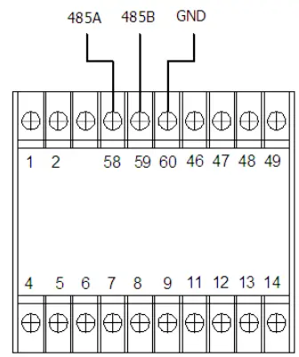
Notes:
- For communication with the master unit, user can choose RS-485 to RS-232 converter or RS485 to USB adapter to use.
- For expand the number of devices in the communication network, a signal repeater can be used.
- Full range of BJ-19… meter RS485 PIN number is 58,59,60
- Due to product modifications or special requirements, the interface pin place may be change. For details, please refer to product label on the rear side
MODBUS © Protocol
Modbus RTU Frame Format:
|
Address code |
1 BYTE |
Slave device address 1-247 |
|
Function code |
1 BYTE |
Indicates the function codes like read coils
/ inputs |
|
Data code |
4 BYTE |
Starting address, high byte Starting address, low byte Number of registers, high byte Number of registers, low byte |
| Error Check code | 2 BYTE | Cyclical Redundancy Check ( CRC ) |
MODBUS FUNCTIONS:
| Code | Meaning | Description |
|
FUNCTION 01 |
Read Coil Status |
Only valid when equipped DO port |
| FUNCTION 02 | Read Input Status | Only valid when equipped DI port |
|
FUNCTION 03 |
Reading of n Words |
This function permits to read all the electrical parameters of the BJ194…series. |
|
FUNCTION 05 |
Force Single coil |
Details see chart 6.4
When DO in remote control mode can work |
|
FUNCTION 06 |
Preset Single register |
Disable in default
If need valid this code, please contact Blue Jay Sales Team before your order! |
Note: Float data follow IEEE754, float low bit first, high bit next. (CD AB)
Only read parameter, can be read with “03” command
| Address | Data | Word byte | Description | |
| 32bit int value | ||||
| 0,1 | U | Voltage | 0,1,2,3 | Unit 0.01V |
| 2,3 | I | Current | 4,5,6,7 | Unit 0.1A |
| 4,5 | P | Power | 8,9,10,11 | Unit 0.01W |
| 6,7 | E | Energy | 12,13,14,15 | Unit 0.001KWh |
| 8,9 | R | Resistance | Unit 0.01Ω
R-U/I |
|
|
14,15 |
AH+ |
Unit 0.001Ah
If Current range= 1A, minimum step = 0.001Ah; If current range = 100A, minimum step = 0.1Ah |
||
| 16,17 | AH- | Unit 0.001Ah | ||
| 18,19 | AH_SUM | Unit 0.001Ah | ||
| 20,21 | RIN | Internal
resistor |
Unit 0.01Ω | |
| 22,23 | E+ | Positive
energy |
Unit 0.001KWh | |
| 24,25 | E- | Negative
energy |
Unit 0.001KWh | |
| Address | Data | Word byte | Description | |
| 32bit float value | ||||
| 30,31 | U float | Voltage | Unit V | |
| 32,33 | I float | Current | Unit A | |
| 34,35 | P float | Power | Unit W | |
| 36,37 | E float | Energy | Unit KWh | |
| 38,39 | R | Resistance | Unit Ω
R-U/I |
|
|
44,45 |
AH+ |
Unit Ah Current range= 1A,
minimum step = 0.001Ah; Current range = 100A, minimum step = 0.1Ah |
||
| 46,47 | AH- | Unit Ah | ||
| 48,49 | Ah_Total | Unit Ah | ||
| 50,51 | RIN | Internal resistor | Unit Ω | |
| 52,53 | E+ | Positive energy | Unit KWh | |
| 54,55 | E- | Negative energy | Unit KWh |
| Other | ||||
|
60,61 |
DIDO |
DO/DO status |
56,57,58,59 |
BIT8-BIT14 for DI status BIT0-BIT7 for DO status 0 for opened,
1 for closed. |
Read and write parameters, can be read with “03” command, and modified with “06” command
| Address | Data | Type | Byte | Description |
| 1000 | Voltage range | Int | 1 | 1-9999V |
| 1001 | Current range | Int | 1 | 1-9999A |
| 1002 | Decimal point position | Int | 1 | 0-3 |
| 1003 | MODBUS Id | Int | 1 | 1-247 |
|
1004 |
Baud rate |
Int |
1 |
0:1200
1:2400 2:4800 3:9600 4:19200 |
|
1005 |
Data format |
Int |
1 |
0:n.8.1
1:o.8.1 2:e.8.1 3:n.8.2 |
| 1006 | Password | Int | 1 | 0-9999 |
|
1007 |
Screen display mode |
Int |
1 |
0-9999:
0 manual switching, Other numbers for seconds of automatic switching |
| 1008 | Backlight display time | Int | 1 | 0-9999min |
| 1009 | Reserved | / | / | / |
|
1010 |
DO1 Pickup time unit DO1_UTD.p |
Int |
1 |
0: sec
1: min 2: hour |
| 1011 | DO1 Pickup time | Int | 1 | 0-999.9 |
|
1012 |
DO1 Drop out time unit
DO1_UTD.d |
Int |
1 |
0: sec
1: min 2: hour |
| 1013 | DO1 Drop out time | Int | 1 | 0-999.9 |
|
1014 |
DO1 Action logic selection |
Int |
1 |
1: A and B and C 2: A or B or C
3: A and B or C 4: A xor B xor C |
|
| 1015 | DO1 Element_A
Hysteresis |
Int | 1 | Range: 0-9999, Unit 1V, 1A,
0.1kW, 0.1AH, 0.1Ω |
|
| Int | 1 | 23: U
lowe r limit 24: I lowe r limit 25: P lowe r limit 26: AH+ lowe r limit 27: AH- lowe r limit 28: AH_ SU M lowe r limit 29: R lowe r limit 30: Res erve d 31: DI1 Ope ned 32: DI2 Ope ned 33: DI3 Ope ned 34: DI4 Ope ned 35: DI5 Ope ned 36: DI6 Ope ned 37: DI7 Ope ned 38: DO1 Ope ned 39: DO2 Ope ned 40: DO3 |
|||
|
0: U upper limit |
|||||
| 1: I upper limit | |||||
| 2: P upper limit | |||||
| 3: AH+ upper limit | |||||
| 4: AH- upper limit | |||||
| 5: AH_SUM upper limit | |||||
| 6: R upper limit | |||||
| 7: Reserved | |||||
| 8: DI1 closed | |||||
| 9: DI2 closed | |||||
|
1016 |
DO1 Element_A Alarm parameter | 10: DI3 closed
11: DI4 closed 12: DI5 closed |
|||
| 13: DI6 closed | |||||
| 14: DI7 closed | |||||
| 15: DO1 closed | |||||
| 16: DO2 closed | |||||
| 17: DO3 closed | |||||
| 18: DO4 closed | |||||
| 19: DO5 closed | |||||
| 20: DO6 closed | |||||
| 21: DO7 closed | |||||
| 22: DO8 closed | |||||
| Ope ned 41: DO4
Ope ned 42: DO5 Ope ned 43: DO6 Ope ned 44: DO7 Ope ned 45: DO8 Ope ned |
||||
| 46: Always Closed
47: Always Opened |
||||
| 1017 | DO1 Element_A
Alarm value |
Int | 1 | Range: 0-9999,
Unit 1V, 1A, 0.1kW, 0.1AH |
| 1018 | DO1 Element_B
Hysteresis |
Int | 1 | Range: 0-9999,
Unit 1V, 1A, 0.1kW, 0.1AH |
| 1019 | DO1 Element_B
Alarm parameter |
Int | 1 | Refer to < DO1 Element_A Alarm
parameter> |
| 1020 | DO1 Element_B
Alarm value |
Int | 1 | Range: 0-9999,
Unit 1V, 1A, 0.1kW, 0.1AH |
| 1021 | DO1 Element_C
Hysteresis |
Int | 1 | Range: 0-9999,
Unit 1V, 1A, 0.1kW, 0.1AH |
| 1022 | DO1 Element_C
Alarm parameter |
Int | 1 | Refer to < DO1 Element_A Alarm
parameter > |
| 1023 | DO1 Element_C
Alarm value |
Int | 1 | Range: 0-9999,
Unit 1V, 1A, 0.1kW, 0.1AH |
|
1024 |
DO1 Mode |
Int |
1 |
0: OFF
1: Remote control pulse 2: Remote control Latching |
| 1025 | DO1 Pulse width | Int | 1 | Range: 0.1-999.9 sec |
| 1026-
1041 |
DO2 Setting | Int | 1 | Refer to DO-1 setting, reg[1010-
1025] |
| 1042-
1057 |
DO3 Setting | Int | 1 | Refer to DO-1 setting, reg[1010-
1025] |
| 1058-
1073 |
DO4 Setting | Int | 1 | Refer to DO-1 setting, reg[1010-
1025] |
| 2000 | Reset energy counter
(Unreadable) |
Int | 1 | Write 0x0A0A,(2570 in Dec) |
| 3000 | Reset AH counter
(Unreadable) |
Int | 1 | Write 0x0A0A,(2570 in Dec) |
SAFETY CONSIDERATIONS
All installation specification described at the previous chapters named:
INSTALLATION AND STARTUP, OPERATION MODE and SPECIFICATIONS.
Note that with the instrument powered on, the terminals could be dangerous to touching and cover opening actions or elements removal may allow accessing dangerous parts. This instrument is factory-shipped at proper operation condition.
MAINTENANCE
The 195-X does not require any special maintenance. No adjustment, maintenance or repairing action should be done when the instrument open and powered on, should those actions are essential, high-qualified operators must perform them.
Before any adjustment, replacement, maintenance or repairing operation is carried out, the instrument must be disconnected from any power supply source.
When any protection failure is suspected to exist, the instrument must be immediately put out of service. The instrument’s design allows a quick replacement in case of any failure.
TECHNICAL SERVICE
For any inquiry about the instrument performance or any failure, contact to Blue Jay’s technical service.
Blue Jay – After-sales service
E-mail: [email protected]
Tel:+0086-023-67628702
www.cqbluejay.com
Add: 1802,Building 2,No.88,Jianxin East Road,Chongqing,400020,China