![]() Assembly instruction and user manual
Assembly instruction and user manual
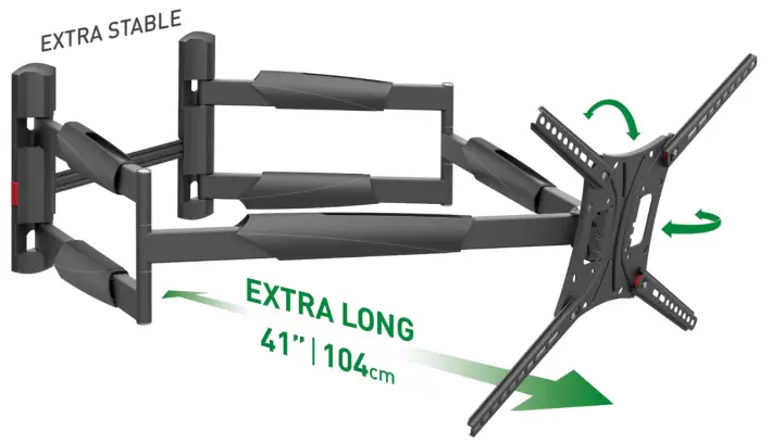
Extra Long and Stable
Premium TV Wall Mount
Full Motion: Extension, Swivel & Tilt
Contents
BM466XP Extra Long and Stable Premium TV Wall Mount
For more information: barkanmounts.com
If you are satisfied with the product, please give us a 5 stars ***** rating on the website you bought it from. If you are not satisfied please contact us at https://www.barkanmounts.com/support and we will solve the problem for you.

CAUTION This Mount is intended for use only with the maximum weight indicated. Using heavier products might cause injury.
ATTENTION! Please read the following.
WARNING!
Disregarding the safety and assembly instructions may result in the falling of, and/ or damage to your electrical appliance. Opening the package represents your undertaking to closely read and follow the instructions. This mount is not intended for use in public places. For Safety Instructions, warranty and further information, go to: www.barkanmounts.com › Support › Safety Instructions & Warranty
Caution
This mount is intended for use only with the maximum weight as indicated. Using heavier products might cause injury.![]()
![]() Do not install on walls and ceilings made of: gypsum board, drywall, light processed blocks, silicate boards/bricks, a damp wall, weak or very old blocks or wooden panel! For installation on gypsum or light processed blocks please consult with an authorized installer or appropriate building specialist to install the product.
Do not install on walls and ceilings made of: gypsum board, drywall, light processed blocks, silicate boards/bricks, a damp wall, weak or very old blocks or wooden panel! For installation on gypsum or light processed blocks please consult with an authorized installer or appropriate building specialist to install the product.
Included Parts not to scale 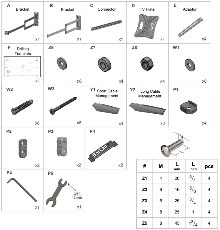
Required Tools

Connect the TV plate to the back of the TV

- Continue according to your TV mounting hole pattern.
 1a 75×75 mm up to 200X200 mm (inclusive) hole pattern.
 1b Hole pattern above 200×200 mm up to 600×400 mm:
- Disassemble the screws.

- connect the 4 adaptors to the TV plate, and reassemble the screws.
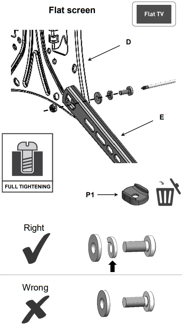

Position the adaptors according to your TV’s hole pattern.
 For additional positioning options please turn to the last page.
Connect the TV plate with the adaptors to the TV in all 4 connection holes.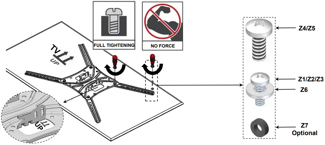
- Disassemble the screws.
- Disassemble the screws from Bracket (B).
Connect Bracket (B) to Bracket (A). * For Corner installation please turn to the page 12.
 - Connector assembly
Connect the connector )C) to the bracket (A+B), make sure that the tab is inserted into the slot.
- Install the bracket on the Wall
Measure the distance between the location of the TV’s mounting holes’ center (marked on the Drilling Template) and the bottom of the TV, in order to set the required height of the TV.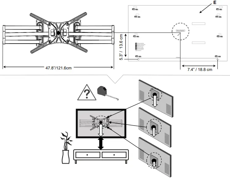 https://www.barkanmounts.com/faq
 - Follow the steps according to your wall type.
 Make sure all holes are drilled inside the studs
 Mark the holes on the wall according to the required height.
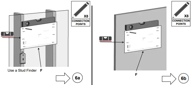
 Assemble the wall plate plastic covers.
 Weight test
Apply force on the upper part of the bracket and make sure it is well connected.
- Place two nuts (Z8) in the nut-housing (P2).

- Assemble the nut-housing (P2) make sure that the tab is inserted into the slot.

- Assemble part (P3) on the nut- housings (P2). push P3 down until the small part that looks like an upside down “T” passes the highlighted tooth.

- Place the bracket upright and connect the TV plate with the TV.

- Secure the TV by inserting and tightening 2 screws on each side of the mount. Tightening the screws in order to create the necessary friction for the tool free tilt mechanism.

- Place the TV cables in the cable management.

- Assemble the cable management on the mount.

- Level the TV according to your desired positioning.

Optional – Corner installation
Functionality may vary depending on the distance from the corner.

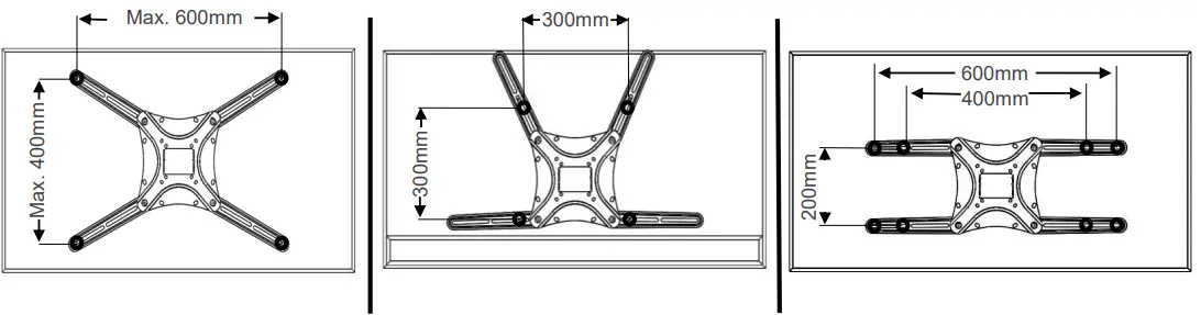
BACKSCREEN CONNECTION POSITIONING OPTIONS
All TV backscreen connections are in millimeters (Width x Height). There are a few sizes of TV plates available. The backscreen connections in position 1 are included in some of the different TV plates, according to their size, and do not require the use of the 4 adapters (marked in blue).
 www.barkanmounts.coim/support
![]()