Azure Wave AW-CU300V2-EVB Evaluation Board User Guide
Revision History
| Version | RevisionDate | Description | Initials | Approved |
| 01 | 2020/07/23 |
|
Renton Tao | N.C. Chen |
| 02 | 2021/11/29 |
|
Renton Tao | N.C. Chen |
Contents
- System Setup
- Normal Link Test
- Re-write Flash for Other Purpose
- WLAN RF Test (w/ MFG FW)
- EVB Attachment
Contents
System Setup
Hardware Requirements
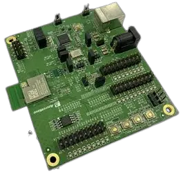
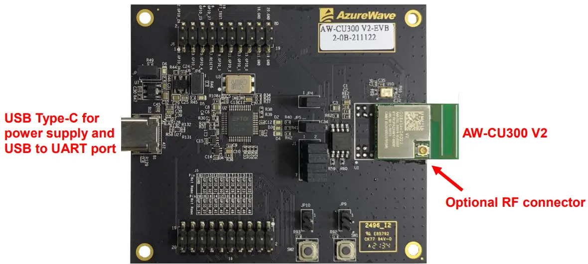
- AW-CU300V2-EVB
- Windows system (OS later than Windows XP) for Labtool.
- Vector Signal Analyzer/WLAN analyzer for transmit measurements.
- WLAN signal generator for receiver measurements.
- RF isolation chamber for receive measurements.
- RF attenuators
- RF cable
Environment set up
Download and Install FTDI VCP Drivers (FT2232D)
Install the driver manually. You can get the driver from FTDI’s web site.
https://www.ftdichip.com/Drivers/VCP.htm
Verifying Driver Installation:
To verify that driver installation has completed successfully, you can open the “Device Manager” (right-click My Computer, select Properties). In the System Properties windows, select Hardware, Device Manager. Two “USB Serial Port” should be listed under MY-PCPorts (COM & LPT)
Normal Link Test
Open OS terminal and set USB comport (reference to the page9), set baud-rate as 115200 Enter cmd “help” on the screen to see a full list of commands available for use
Re-write Flash for Other Purpose
For other MCU test purpose, user has to re-write the flash to update the MCU function. To re-write flash, programming through MCU JTAG interface is the suggested method.
Download Libusb-win32
To identify the COM port of FT232 for JTAG interface, libusb is needed.
You can get the driver from libusb-win32’s web site.
https://sourceforge.net/projects/libusb-win32
Install Libusb-win32
Verifying Driver Installation:
To verify that driver installation has completed successfully, you can open the “Device Manager” (right-click My Computer, select Properties). In the System Properties windows, select Hardware, Device Manager. One “USB Serial Converter A” should be listed under MY-PCPorts (lib usb-win32 devices)

Download and Install Cygwin
Install Cygwin:
- Download Cygwin from: https://www.cygwin.com/setup-x86.exe (for x86 32-bit systems) or https://www.cygwin.com/setup-x86_64.exe (for x86 64-bit systems)
- Select the option Install from Internet
- Use default installation path: c:cygwin. If you chose an alternate installation directory, please make sure that there are no spaces in the path.
- Pick the Local Package Directory (this is the download cache directory)
- Select the option Direct Connection
- Select any mirror you want to use
- Add additional packages to the default selection:
Click “Next”. The Cygwin Setup window will show the progress as each package gets installed.
Note: If you are not familiar with cygwin, please visit https://cygwin.com/ for additional information and details. In particular, the Cygwin User Guide (https://cygwin.com/cygwin-ug-net/) is a good resource for new users.
Insert file “OpenOCD.zip” for FW burn in.
Unzip “CU300_OpenOCD.zip” and put “readelf.exe” to C:cygwinbin
Unzip “CU300_OpenOCD.zip” and put them to C:cygwin
Execute Cygwin,bat
Move to working folder
Burn in FW for RF testing
Example
Link test with RF normal FW(default):
Check config_normal_RTC.txt, layout.txt … 6 files in the Open OCD folder
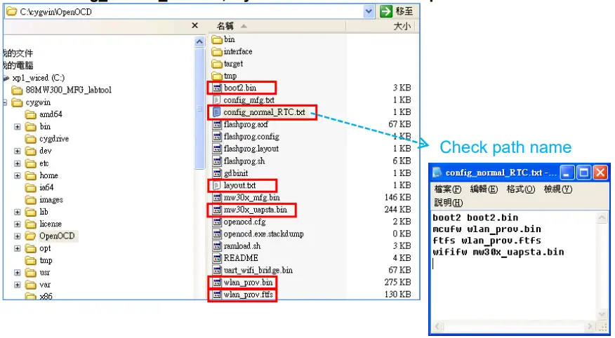
Key in cmd to burn in normal FW.
Now you can perform normal link testing. (Needs to re-boot the EVB after burning in)
RF test with MFG FW:
For RF testing with MFG FW, you needs to re-burn in the FW as below. Check config_mfg.txt, layout.txt … 5files in Open OCD folder
Key in cmd to burn in MFG FW.
Check if all files are burn in correctly

Now you can perform MFG RF testing. (Needs to re-boot the EVB after burning in)
RF Test (w/MFG FW)
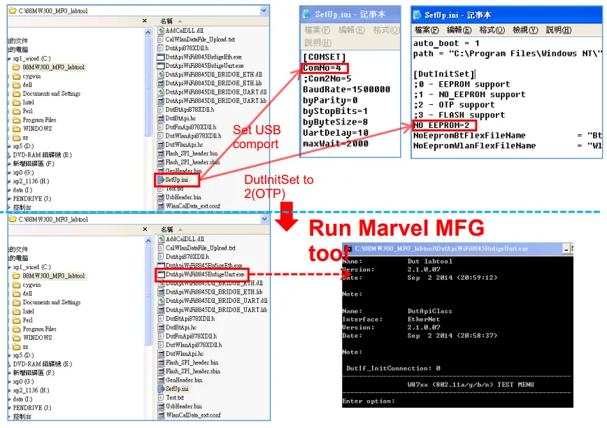
Run Lab tool in Windows OS.
Generate 802.11b/g/n Packet commands
a. Tx on CH 6 at 10 dBm with a CCK-11Mbps data rate in 20 MHz BW mode on WiFi
25 // Stop Tx112 0 // Set to 20 MHz BW 12 6 // Set to CH 6 22 6 10 0 // Set to CH 6 at 10 dBm Output Power with CCK/BPSK Data Rate on WiFi
b. Tx on CH 100 at 8 dBm with a MCS7 Data rate in 20 MHz BW Mode on WiFi
25 // Stop Tx 112 0 // Set to 20 MHz BW 12 13 // Set to CH 13 22 13 8 1 // Set to CH 13 at 8 dBm Output Power with OFDM Data Rate on WiFi 25 1 22 // Tx at MCS 7
Data rate set up
B mode & G mode:
| 1Mbps | 5.5Mbps | 11Mbps | 6Mbps | 9Mbps | 12Mbps | 18Mbps | 24Mbps |
| 1 | 3 | 4 | 6 | 7 | 8 | 9 | 10 |
| 36Mbps | 48Mbps | 54Mbps | |||||
| 11 | 12 | 13 | |||||
N mode:
| MCS0 | MCS1 | MCS2 | MCS3 | MCS4 | MCS5 | MCS6 | MCS7 | |
| 15 | 16 | 17 | 18 | 19 | 20 | 21 | 22 |
After you type above command, you can measure the 802.11b/g/n packet by your RF test instrument (exp: Agilent 4010, IQview…).
Generate 802.11 b/g/n continuous symbol Commands
a. Cont. Tx on CH 7 at 8 dBm with a MCS7 Data rate in 20 MHz BW Mode on WiFi
17 // Stop Cont. Tx 25 // Stop Tx 112 0 // Set to 20 MHz BW 12 7 // Set to CH 36 22 7 8 1 // Set to CH 36 at 8 dBm Output Power with MCS Data Rate on WiFi 25 1 22 // Tx at MCS 7 25 // Stop Tx 17 1 22 // Cont. Tx at MCS7 17 // Stop Cont. Tx
Others Commands
- Command 45-Check the MAC
- Command 99-Quit the test mode/ Quit the MFG tool
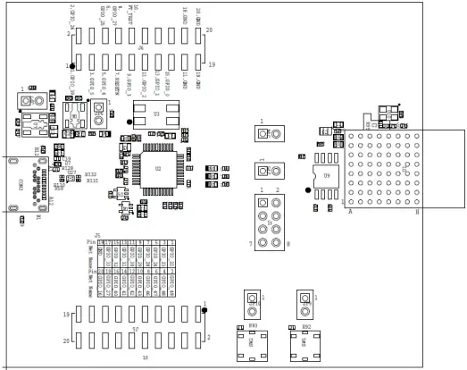
EVB Attachment


The information contained herein is the exclusive property of AzureWave and shall not be distributed, reproduced, or disclosed in whole or in part without prior written permission of AzureWave.
![]()