Anolis Arcsource Outdoor 16MC Integral Power Supply Instruction Manual

Contents
MOUNTING – USING YOKE
Fixture must be installed by a qualified electrican in accordance with all national and local electrical and construction codes and regulations. This device falls under class one and must be grounded!
Use an Allen key 6 to release M8 tilting lock on each side of luminaire and adjust tilt of LED module in range of +35°/-90°.
Mount the fixture via suitable mounting holes. Ensure that you are mounting the fixture to a secure and non-flammable surface.
Fasten the Yoke of the fixture to the surface by three screws
Use fasteners that are appropriate for use with your mounting surface.
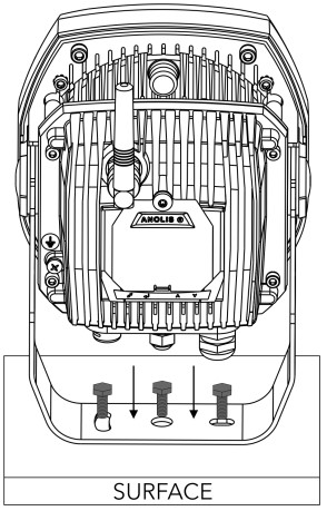
Fasten the Yoke of the fixture to the surface by three screws.
MOUNTING – USING FLOOR STAND
Use fasteners that are appropriate for use with your mounting surface.
Mount the luminaire to the Floor stand as illustrated on picture above and fasten it by nut with washer to bolt on floor stand.
Mount the luminaire to the Floor stand as illustrated on picture above and fasten it by nut with washer to bolt on floor stand.
ArcSource Outdoor 16MC Integral mounted on the Floor Stand.
MOUNTING – USING LAND SPIKE 100 MM / 130 MM
Land Spike 100mm and Land Spike 130mm.
Insert the Land Spike into ground. Underground part of Land Spike should be placed perpendicularly into the ground. (if you need to use tools to insert spike in the ground, use of some protective layer, and applying pressure in the middle is recommended to prevent damaging of land spike)
Mount the luminaire to the Land Spike as illustrated on pictre above and fasten it by two screws M8x20 with washers and spring washers.

ArcSource Outdoor 16MC Integral mounted on the Land Spike.
MOUNTING – USING TENON ADAPTOR
DIAMETER 63 – 80 MM / 80 – 106 MM
Tenon Adaptor 63 – 80 mm and Tenon adaptor 80 – 106 mm
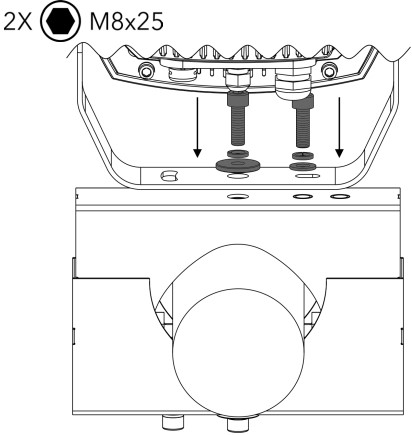
Slide the Tenon adaptor (mortise) of suitable size on a tenon (e.g. top of a metal post) and fasten in with three screws included in the adaptor.
Mount the luminaire to the Tenon Adaptor as illustrated on picture above and fasten it by two screws M8x25 with washers and spring washers.

ArcSource Outdoor 16MC Integral mounted on the Tenon Adaptor.

MOUNTING – USING POLE CLAMP
DIAMETER 63 – 80 MM / 80 – 105 MM
Disassemble the Pole clamp by unscrewing both nuts from bolts.

Mount the Pole Clamp to a pole and fasten it by screwing both nuts with washers back to their bolts. Adjust the Pole clamp to ensure its correct position before tightening it completely
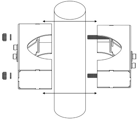
When in correct position, tighten both nuts completely.
Place the yoke of the luminaire to the Pole Clamp as illustrated on picture above and fasten it by two screws M8x25 with washers and spring washers.
ArcSource Outdoor 16MC Integral mounted on each side of Pole Clamp.

CONNECTION

Single luminaire connection.
Connect DMX IN and Power cable to a Junction box and Power/data cable from the Junction box to the luminaire.
Multiple luminaire connection.
Use power/data cable for connection between Junction boxes as illustrated on picture bellow. Notice the change of connection between first two and all following junction boxes of the daisy chain line.
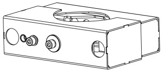
Removing the Cover of Junction Box
Open the Junction Box by unscrewing 4 M4x20 screws and lifting up the cover.
Install Housing
Use fasteners that are appropriate for use with your mounting surface.
Mount the Junction Box to a surface via two mounting holes and suitable fasteners.
Strip these lenghts for wire connections
| Power Connection – Power IN | |||
|
L |
N |
GROUND |
|
| Core (EU) | Brown | Blue | Green/Yellow |
| Core (US) | Black | White | Green |
DMX CONNECTION
|
0 V |
D- |
D+ |
| Data Ground | Data – | Data + |
Cable CE/US Leader – LED Output
|
WIRE |
DATA AND POWER CONNECTION |
| Brown | Live |
| Blue | Neutral |
| Yellow/Green | Ground |
| Red | + |
| White | – |
| Shielding | 0 |
Wiring connection – single LED unit

EU color code shown
Connection scheme for the installations of single luminaire.
Wiring connection – Daisy chain – First Junction box

EU color code shown
Connection scheme for the first Junction Box in daisy chain line.
Wiring connection – Daisy chain – Following Junction boxes
EU color code shown
Connection scheme for each following Junction Box in daisy chain line. Only power/data cables are used.
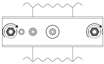
Cable gland installation
Use wrench size 24 for cable gland M20x1.5
Install Cable glands individually!
Apply Loctite 5331 thread sealant on the plastic holder and Loctite 577 thread locking compound on the gland body in the indicated locations prior to assembly.
Failure to properly install cable glands will result in failure of the water tight seal!
Close junction box
Install safety cover and top cover back.
Before applying the torque, make sure the thread is clean and functional.
INSTALLATION OF ACCESSORIES
Top Hat and Half Top Hat.
(Identical installation instructions)
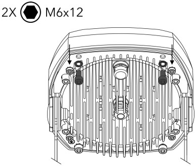
- Unscrew 4 M6x12 screws from rear side of the luminaire as highlighted on picture above.
- Slide the accessory on the luminaire from a side.
- Fasten the top side of accessory to the rear side of luminaire with two M6x12 screws and spring washers.

- Slide a holder of accessory on the rear side of luminaire.

- Fasten the holder to the luminaire by two M3x6 screws with toothed lockwashers.
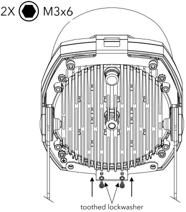
- Fasten the bottom side of accessory to the rear side of luminaire and installed holder. Use two M6x12 screws, one with spring washers and one with toothed lockwasher.
- Unscrew two M6x12 screws from the rear side of luminaire as highlighted on a picture above.
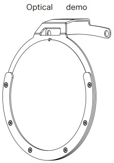
- Slide the Optical demo set on the luminaire.

- Fasten the accessory to the rear side of luminaire with two original screws and washers.

- Slide an optical foil into Optical demo set

ArcSource Outdoor 16MC Integral with Optical demo set.
