![]() MAX96717 DPHY Evaluation Kit
MAX96717 DPHY Evaluation Kit
Evaluates: MAX96717F
Click Buy Parts, Request Quote and Sample from Maxim Integrated to ask an associate for production status of specific part numbers.
Contents
General Description
The MAX96717 DPHY evaluation kit (EV kit) provides a proven design to evaluate the MAX96717 high-bandwidth gigabit multimedia serial link (GMSL) serializer with spread spectrum and full-duplex control channel using a standard FAKRA coaxial (Coax) or HMTD cable. The EV kit also includes Windows® 7 and Windows® 10 software that provides a simple graphical user interface (GUI) for exercising features of the device. The EV kit comes with a MAX96717, MAX96717F, MAX96717K or MAX96717R IC installed.
For complete GMSL evaluation using a standard FAKRA coaxial cable or HMTD cable, order the MAX96717 Coax EV kit and a companion deserializer board (MAX96716 Coax EV kit referenced in this document).
Note: In the following sections, “serializer” refers to camera serializer interface (CSI) serializer, including MAX96717, MAX96717F, MAX96717K and MAX96717R. “Deserializer” refers to CSI deserializer MAX96716 and its variants.
This document applies to both Coax and HMTD evaluation kits.
Coax cable is also referenced in this document.
Benefits and Features
- Ability for Serializer to send GMSL data to Deserializer, converting it into MIPI CSI-2
- Windows 10 or Higher Compatible Software Support
- USB Controlled Interface (Cable Included)
- Powerful and Simple GUI for Comprehensive Device Feature Evaluation
- Board Powered by USB, 12V Wall Adapter or External Power Supply
- Proven PCB Layout
- Fully Assembled and Tested
Note: Coax EV kits are configured to use PoC and FAKRA connectors. For HMTD connector, order HMTD specific EV kits found in the Ordering Information section.
Ordering Information appears at end of data sheet.
MAX96717 EV Kit Files
| FILE | DECRIPTION |
| MAXSerDesEV-GMSL_Vxxxx_Install.exe | Installs the EV kit software (GUI) onto Windows 10 or higher computers. Includes GUI user’s guide, microcontroller firmware, and documentation. |
| MAXSerDesEV-GMSL.exe | GMSL graphical user interface (GUI) program |
 |
 |
 |
 |
Quick Start
This procedure applies to both Coax and HMTD EV kits.
Figure 5 shows a typical application that uses the CSI serializer with the CSI deserializer.
Required Equipment
The following equipment is required to successfully use the MAX96717 DPHY EV kit in a serial link coax cable configuration:
- MAX96716 DPHY EV kit rev A
- FAKRA Cable Assembly
- PC with Windows 10 or higher and GMSL2 Software
- PC running GMSL Software
- Power supply source (500mA USB port, 5V/1A DC Supply or 12V barrel jack DC supply [provided])
- Micro-USB cable
Procedure
- Follow the steps below to verify board operation.
- Download and install the latest GMSL EV kit software from www.maximintegrated.com or contact Maxim Applications. Follow the GMSL GUI User’s Guide instructions.
- Verify that jumpers on the serializer board are in their default positions, as shown in Figure 2, and SW1 is in the OFF position.
- Verify that jumpers on the deserializer board are in their default positions, and SW1 is in the OFF position.
- Set up the system as below:
• Connect FAKRA cable from FAKRA PCB connector from serializer to deserializer (Link A or Link B).
• Connect +12V wall power supply into the POWER connector. - Turn SW1 to the ON position on both serializer and deserializer EV kits.
- Verify that all of the power LEDs and red Teensy LED are illuminated, indicating that the board is powered, and Teensy uC is powered on both serializer and deserializer.
- Verify the LOCK LED on both serializer and deserializer EV kits are illuminated, indicating that the link is successfully established. If the LOCK_LED is OFF or ERR_LED is ON, refer to the Troubleshooting section.
- Start the GMSL GUI software.
- When the GUI opens, it automatically searches for any active listener in both I2C and UART mode and identifies a valid GMSL product. Once the serializer and deserializer are identified, they are shown as tabs in the GUI.
- Read register 0x00 in both deserializer and serializer to ensure both devices are active.
- Basic bring-up is complete. Refer to the GMSL GUI User’s Guide, GMSL Bring-up Guide, the latest datasheet, or contact Maxim Applications for additional details.
Configuration (CFG) Pin Settings
The serializer’s CFG pins use the pin voltage latched at power-up to configure the device. On-board I2Cconfigurable digital potentiometers or 0402 resistors set the configuration (CFG) pin voltage levels. By default, the board is wired to use the digital potentiometers.
The CFG states can be configured using the GMSL 2 GUI. Use the following GUI menu path: Tools > Set CFG Pin Levels.
To switch between using the digital potentiometer or resistor network to set CFG states, use 0Ω resistors to connect the CFG0/1 nets. The voltage on the CFG pins can be monitored on the CFG0 and CFG1 test points or on the 2×12 MFP header (J1).
If the serializer is not identified in the GUI, it is still possible to write to the CFG pins. For more information, refer to the Troubleshooting section.
The voltage levels scale with VDDIO. Tables 1-5 indicate the voltage levels necessary to configure the serializer for different modes of operation.

Table 1 MAX96717/717F/717K CFG0 Pin Input Map
| CFG0 INPUT VOLTAGE (PERCENT OF VDDIO) | SUGGESTED RESISTOR VALUES (1% TOLERANCE) |
MAPPED CONFIGURATION | |||||
| MIN | TYP | MAX | R1 (Ω) | R2 (Ω) | I2CSEL | ROR/XTAL | DEVICE ADDRESS |
| 0% | 0% | 11.7% | OPEN | 10000 | I2C | ROR | 0x80 |
| 16.9% | 20.2% | 23.6% | 80600 | 20500 | 0x84 | ||
| 28.8% | 32.1% | 35.5% | 68100 | 32400 | XTAL | 0x80 | |
| 40.7% | 44.0% | 47.4% | 56200 | 44200 | 0x84 | ||
| 52.6% | 56.0% | 59.3% | 44200 | 56200 | UART | ROR | 0x84 |
| 64.5% | 67.9% | 71.2% | 32400 | 68100 | 0x80 | ||
| 76.4% | 79.8% | 83.1% | 20500 | 80600 | XTAL | 0x84 | |
| 88.3% | 100% | 100% | 10000 | OPEN | 0x80 | ||
Table 2. MAX96717R CFG0 Pin Input Map
| CFG0 INPUT VOLTAGE (PERCENT OF VDDIO) | SUGGESTED RESISTOR VALUES (1% TOLERANCE) |
MAPPED CONFIGURATION | |||
| MIN | TYP | MAX | R1 (Ω) | R2 (Ω) | DEVICE ADDRESS |
| 28.8% | 32.1% | 35.5% | 68100 | 32400 | 0x80 |
| 40.7% | 44.0% | 47.4% | 56200 | 44200 | 0x84 |
Table 3. MAX96717/717K CFG1 Pin Input Map
| CFG1 INPUT VOLTAGE (PERCENT OF VDDIO) | SUGGESTED RESISTOR VALUES (1% TOLERANCE) |
MAPPED CONFIGURATION (GMSL2 OPERATING MODE) | |||||
| MIN | TYP | MAX | R1 (Ω) | R2 (Ω) | CXTP | DATA RATE (GBPS) | TUNNEL/PIXEL MODE |
| 0% | 0% | 11.7% | OPEN | 10000 | STP | 3 | Tunnel |
| 16.9% | 20.2% | 23.6% | 80600 | 20500 | 6 | ||
| 28.8% | 32.1% | 35.5% | 68100 | 32400 | 3 | Pixel | |
| 40.7% | 44.0% | 47.4% | 56200 | 44200 | 6 | ||
| 52.6% | 56.0% | 59.3% | 44200 | 56200 | COAX | 3 | Tunnel |
| 64.5% | 67.9% | 71.2% | 32400 | 68100 | 6 | ||
| 76.4% | 79.8% | 83.1% | 20500 | 80600 | 3 | Pixel | |
| 88.3% | 100% | 100% | 10000 | OPEN | 6 | ||
Table 4. MAX96717F CFG1 Pin Input Map
| CFG1 INPUT VOLTAGE (PERCENT OF VDDIO) | SUGGESTED RESISTOR VALUES (1% TOLERANCE) |
MAPPED CONFIGURATION (GMSL2 OPERATING MODE) | |||||
| MIN | TYP | MAX | R1 (Ω) | R2 (Ω) | CXTP | DATA RATE (GBPS) | TUNNEL/PIXEL MODE |
| 0% | 0% | 11.7% | OPEN | 10000 | STP | 3 | Tunnel |
| 16.9% | 20.2% | 23.6% | 80600 | 20500 | |||
| 28.8% | 32.1% | 35.5% | 68100 | 32400 | 3 | Pixel | |
| 40.7% | 44.0% | 47.4% | 56200 | 44200 | |||
| 52.6% | 56.0% | 59.3% | 44200 | 56200 | COAX | 3 | Tunnel |
| 64.5% | 67.9% | 71.2% | 32400 | 68100 | |||
| 76.4% | 79.8% | 83.1% | 20500 | 80600 | 3 | Pixel | |
| 88.3% | 100% | 100% | 10000 | OPEN | |||
Table 5. MAX96717R CFG1 Pin Input Map
| CFG0 INPUT VOLTAGE (PERCENT OF VDDIO) | SUGGESTED RESISTOR VALUES (1% TOLERANCE) |
MAPPED CONFIGURATION | |||
| MIN | TYP | MAX | R1 (Ω) | R2 (Ω) | TUNNEL/PIXEL MODE |
| 52.6% | 56.0% | 59.3% | 44200 | 56200 | Tunnel |
| 88.3% | 100% | 100% | 10000 | OPEN | Pixel |
Table 6. Serializer Jumper Descriptions
The following table contains details of all the connectors, jumpers, and test points of the EV kit. The power configuration of the EV kit hardware can be reconfigured to allow external supply connections. Figure 6 shows the power connection options.
| JUMPER | SIGNAL | DEFAULT POSITION | FUNCTION |
| POWER | +12V, EXT PWR, 5V USB, | +12V | Power to supply voltage VSUP. |
| J1 | MFP | Open | Connection for MFP signals. |
| J2 | HMTD SIOA (+/-) | Open | HMTD connector for SIOA GMSL signal. |
| J3 | USB Connection | Open | Connection from PC to TEENSY and +5V USB connection. |
| J4 | SAMTEC Connector | Open | Connector for MIPI signals and MFP (SPI, I2C, GPIOs) signals. |
| J5 | External 12V Input | N/A | 12V DC input for board power. |
| J6 | External Supply Input | Open | Header for GND connection and optional external voltage. |
| VDDIO | VDDIO, 1.8V, 3.3V | 3.3V | Connection between VDDIO, 1.8V and 3.3V. |
| VDD | VDD, 1V, 1.2V | 1.2V | Connection between VDD, 1V and 1.2V. |
| VDD_REF | VDD_REF | 3.3V | Connection between VDD_REF and 3.3V for I2C/UART lines. |
| RX_SDA | UART TX, I2C SDA | TNZ_SDA | Selection of I2C or UART connection to TEENSY. |
| TX_SCL | UART RX, I2C SCL | TNZ_SCL | Selection of I2C or UART connection to TEENSY. |
| EXP | SDA_RX, SCL_TX | Open | External I2C or UART connections. |
| EXT_UC | SDA, SCL, GND, VDD_REF | Open | External I2C or UART connections through the levels translator. |
| JAP | COAX SIOA+ | Open | GMSL and PoC connection for COAX Link A. |

Troubleshooting
If the MAX96717 EV kit PCB fails to power-up or does not function properly, try the appropriate remedial actions below.
- Verify the board’s red power switch (SW1) is set to the ON position.
- Verify that the device is powered properly. Ensure that the voltages are within their operating ranges at all device pins. Verify that power LED is illuminated and/or measure voltage rail jumpers.
- Check that all jumpers are correctly set. Refer to the default jumper settings table in the serializer and deserializer EV kit data sheets. Also, ensure that all jumpers are firmly attached. Replace loose or damaged jumpers, if necessary.
- Check that the USB cable is properly seated in the USB port.
- Check that the coax/STP cable connection between serializer and deserializer is properly secured.
- Verify that the DUT has not been inadvertently put into Teensy reset mode. The board’s TEENSY_RST button should only be pressed when firmware is being flashed to the DUT. If the button is pressed during normal operation, the device goes into Teensy reset mode. Power cycle the board to resume normal operation with the current firmware.
- Validate that the correct CFG pin voltages are being used to configure the serializer. Check the method of biasing the CFG voltage at powerup. Measure the voltages at the pins. For details, refer to the Configuration (CFG) Pin Settings section.
- If the CFG pin settings are incorrect, but the device is not identified in the GUI, proceed to the Configuration (CFG) Pin Settings section and set the desired CFG state values. Reset the part and verify if the GUI automatically identifies the device. If not, use the following menu path to locate the device: Options tab > Identify Devices. The low-level Commands tab can be monitored to see if I2C writes to the CFG pots are successful.
- Check that the I2C/UART jumpers match the DUT communication mode (SCL/SDA for I2C, TX/RX for UART).
- Check that the AC coupling capacitors are populated correctly and routing the serial link to the correct connector for Coax or STP mode. For coax boards, capacitors C12 and C13 should be populated. For STP boards, capacitors C3 and C19 should be populated (MAX96717 EV kit boards are shipped with the correct capacitors installed.).
- Check that the microcontroller firmware is active by observing the blinking red Teensy LED at power-up. If the LED is not blinking, refer to the available software documentation to reprogram the microcontroller.
- Check that the PC is detecting the COM port when the micro-USB cable is connected. Use the Windows Device Manager to check COM port status.
- Power-cycle the board and reopen the GUI.
- Try a new or different serializer or deserializer board.
MAX96717 DPHY EV Kit Package Contents
| ITEM DESCRIPTION | QTY |
| MAX96717 DPHY EV kit (or a variant) | 1 |
| Micro-USB Cable | 1 |
| 12V DC Wall Supply | 1 |
| Coax Cable for Coax EV kits or HMTD cable for HMTD EV kits | 1 |
Major Component Suppliers
| SUPPLIER | PHONE | WEBSITE |
| Rosenberger Hochfrequenztechnik GmbH | 011-49-86 84-18-0 | www.rosenberger.de |
| TDK Corp. | 547-803-6100 | product.tdk.com/info/en/catalog/index.html |
| Diodes Inc. | 972-987-3900 | www.diodes.com |
| Murata Electronics North America, Inc. | 770-436-1300 | www.murata-northamerica.com |
| Coilcraft | 847-639-6400 | www.coilcraft.com |
| Panasonic North America | N/A | na.panasonic.com/us/ |
| ECS, Inc. | 913-782-7787 | www.ecsxtal.com |
| Vishay | 1-402-563-6866 | www.vishay.com |
| KYOCERA | N/A | https://global.kyocera.com/ |
| Sullins Electronics Corp | 760-744-0125 | www.sullinscorp.com |
Ordering Information
| PART | TYPE |
| MAX96717-AAK-EVK#** | CSI-2 to GMSL2 Serializer DPHY w/COAX |
| MAX96717-ACK-EVK#** | CSI-2 to GMSL2 Serializer DPHY w/HMTD |
| MAX96717K-AAK-EVK#** | CSI-2 to GMSL2 Serializer DPHY w/COAX |
| MAX96717K-ACK-EVK#** | CSI-2 to GMSL2 Serializer DPHY w/HMTD |
| MAX96717F-AAK-EVK# | CSI-2 to GMSL2 Serializer DPHY w/COAX |
| MAX96717F-ACK-EVK#* | CSI-2 to GMSL2 Serializer DPHY w/HMTD |
| MAX96717R-AAK-EVK#** | CSI-2 to GMSL2 Serializer DPHY w/COAX |
| MAX96717R-ACK-EVK#** | CSI-2 to GMSL2 Serializer DPHY w/HMTD |
*Contact factory.
**Future product – contact factory for availability.
MAX96717 EV Kit Bill of Materials (Coax)
| ITEM | QTY | REF DES | VAR STATUS | MAXINV | MFG PART # | MANUFACTURER | VALUE | DESCRIPTION | COMMENTS |
| 1 | 1 | C1 | Pref | 20-0022P-27J | C1005C0G1H220G050 | TDK | 22PF | CAPACITOR; SMT (0402); CERAMIC CHIP; 22PF; 50V; TOL=2%; TG=-55 DEGC TO +125 DEGC; TC=C0G | |
| 2 | 1 | C2 | Pref | 20-0027P-27 | C0402C0G500270JNP; GRM1555C1H270JA01 | VENKEL LTD.;MURATA | 27PF | CAPACITOR; SMT; 0402; CERAMIC; 27pF; 50V; 5%; C0G; -55degC to + 125degC; 0 +/-30PPM/degC | |
| 3 | 22 | C4, C8, C11, C16, C18, C21-C24, C26- C31, C39, C40, C45, C46, C55, C119, C120 | Pref | 20-000U1-DA22 | CGA2B1X7R1C104K050BC; GCM155R71C104KA55 | TDK;MURATA | 0.1UF | CAPACITOR; SMT (0402); CERAMIC CHIP; 0.1UF; 16V; TOL=10%; TG=-55 DEGC TO +125 DEGC; TC=X7R; AUTO; NOTE: PLEASE USE MAXINV 20-000u1-L1A | |
| 4 | 4 | C6, C9, C14, C17 | Pref | 20-00U01-12A | GRM155R71H103JA88 | MURATA | 0.01UF | CAPACITOR; SMT (0402); CERAMIC CHIP; 0.01UF; 50V; TOL=5%; TG=-55 DEGC TO +125 DEGC; TC=X7R | |
| 5 | 14 | C10, C36-C38, C41-C43,
C47-C53 |
Pref | 20-0010U-BA92 | GRT188R61C106KE13 | MURATA | 10UF | CAPACITOR; SMT (0603); CERAMIC CHIP; 10UF; 16V; TOL=10%; TG=-55 DEGC TO +85 DEGC; TC=X5R; AUTO | |
|
6 |
2 | C12, C13 |
Pref |
20-000U1-04A | CGA2B3X7R1H104K050BB; C1005X7R1H104K050BB; GRM155R71H104KE14; GCM155R71H104KE02; C1005X7R1H104K050BE; UMK105B7104KV-FR; CGA2B3X7R1H104K050BE |
TDK;TDK;MURATA;MURATA; TDK;TAIYO YUDEN;TDK |
0.1UF | CAPACITOR; SMT (0402); CERAMIC CHIP; 0.1UF; 50V; TOL=10%; TG=-55 DEGC TO +125 DEGC; TC=X7R | |
| 7 | 1 | C15 | Pref | 20-0001U-CA22 | CGA3E1X7R1V105K | TDK | 1UF | CAPACITOR; SMT (0603); CERAMIC CHIP; 1UF; 35V; TOL=10%; TG=-55 DEGC TO +125 DEGC; TC=X7R; AUTO; NOTE: SET TO OBSOLETE USE MAXINV NO 20- 0001U-BA46 | |
| 8 | 3 | C20, C25, C44 | Pref | 20-002U2-11D | GRM188Z71C225KE43 | MURATA | 2.2UF | CAPACITOR; SMT (0603); CERAMIC CHIP; 2.2UF; 16V; TOL=10%; TG=-55 DEGC TO +125 DEGC; TC=X7R | |
| 9 | 2 | C34, C35 | Pref | 20-0047U-A42 | C3216X5R1E476M160AC | TDK | 47UF | CAPACITOR; SMT (1206); CERAMIC CHIP; 47UF; 25V; TOL=20%; MODEL=C SERIES; TG=-55 DEGC TO +85 DEGC; TC=X5R ;NOTE: THESE PARTS HAVE 28 WEEKS LEAD TIME; MANUFACTURING DELAYS HAVE BEEN REPORTED ON THIS PRODUCT | |
| 10 | 2 | C54, C56 | Pref | 20-004U7-X3 | C1608X5R0J475M080AB; GRM188R60J475ME19; JMK107BJ475MA |
TDK;MURATA;TAIYO YUDEN |
4.7UF |
CAPACITOR; SMT (0603); CERAMIC; 4.7UF; 6.3V; OL=20%; MODEL=C SERIES; TG=-55 DEGC TO +85 DEGC; TC=X5R | |
| 11 | 1 | C57 | Pref | 20-0100U-CA04 | T491X107K025A | KEMET | 100UF | CAPACITOR; SMT (7343-43); ANTALUM CHIP; 100UF; 25V; TOL=10% | |
| 12 | CFG0, CFG1 | Pref | 02-TPMINI5000-00 | 5000 | EYSTONE | N/A | TEST POINT; PIN DIA=0.1IN; TOTAL LENGTH=0.3IN; BOARD HOLE=0.04IN; RED; PHOSPHOR BRONZE WIRE SILVER PLATE FINISH; RECOMMENDED FOR BOARD THICKNESS=0.062IN; NOT FOR COLD TEST;NOTE: SET TO OBSOLETE DUE TO CORRECTION IN STEP MODEL COLOR | ||
| 13 | 2 | D1, D2 | Pref | 30-ES1D-00 | ES1D | FAIRCHILD SEMICONDUCTOR | ES1D | DIODE; RECT; SMA (DO-214AC); PIV=200V; IF=1A | |
| 14 | 1 | D3 | Pref | 30-DFLS140L-00 | DFLS140L | DIODES INCORPORATED | DFLS140L | DIODE; SCH; SMT (POWERDI-123); PIV=40V; IF=1A | |
| 15 | 1 | D4 | Pref | 30-B360B13F-00 | B360B-13-F | DIODES INCORPORATED | B360B-13-F | DIODE; SCH; SCHOTTKY BARRIER DIODE; SMB; PIV=60V; Io=3A; -55 DEGC TO +125 DEGC | |
| 16 | 2 | DS1, DS3 | Pref | 30-SMLP11UTT86-00 | SML-P11UTT86 | ROHM | SML-P11UTT86 | DIODE; LED; SMT; PIV=1.8V; IF=0.02A | |
| 17 | 1 | DS2 | Pref | 30-SMLP11MTT86-00 | SML-P11MTT86 | ROHM | SML-P11MTT86 | DIODE; LED; SMT; PIV=5V; IF=0.02A | |
| 18 | 1 | DS4 | Pref | 30-SMLE13BC8T-00 | SMLE13BC8T | ROHM SEMICONDUCTOR | SMLE13BC8T | DIODE; LED; SML-E1 SERIES; BLUE; SMT (0603); VF=2.9V; IF=0.005A; | |
| 19 | 1 | EV_KIT_BOX1 | Pref | 00-SAMPLE-01 | SRLZR_COAX_HSD_HMTD_BOX | MAXIM | SRLZR_COAX_HSD_HMTD_BOX | EV KIT PACKAGING SET FOR SERIALIZER COAX OR HSD OR_HMTD BOX; LARGE BROWN 15 1/8 inch X 8 3/4 inch X 3 inch | |
| 20 | 3 | EXP, J10,
VDD REF |
Pref | 01-PBC02SAAN2P-21 | PBC02SAAN | SULLINS ELECTRONICS CORP. | PBC02SAAN | CONNECTOR; MALE; THROUGH HOLE; BREAKAWAY; STRAIGHT; 2PINS | |
| 21 | 2 | EXT, GND | Pref | 01-9020BUSS20AWG-00 | 9020 BUSS | WEICO WIRE | MAXIMPAD | EVK KIT PARTS; MAXIM PAD; WIRE; NATURAL; SOLID; WEICO WIRE; SOFT DRAWN BUS TYPE-S; 20AWG | |
| 22 | 1 | EXT_UC | Pref | 01-PBC04SAAN4P-21 | PBC04SAAN | SULLINS ELECTRONICS CORP. | PBC04SAAN | CONNECTOR; MALE; THROUGH HOLE; BREAKAWAY; STRAIGHT; 4PINS; -65 DEGC TO +125 DEGC | |
| 23 | 1 | J1 | Pref | 01-PBC12SAAN12P-21 | PBC12SAAN | SULLINS ELECTRONICS CORP. | PBC12SAAN | CONNECTOR; MALE; THROUGH HOLE; BREAKAWAY; STRAIGHT; 12PINS; -65 DEGC TO +125 DEGC | |
| 24 | 1 | J3 | Pref | 01-198156815P-26 | 1981568-1 | TE CONNECTIVITY | 1981568-1 | CONNECTOR; FEMALE; SMT; MICRO USB STANDARD TYPE B ASSY; RIGHT ANGLE; 5PINS | |
| 25 | 1 | J4 | Pref | 01-QTH03001LDA-17 | QTH-030-01-L-D-A | SAMTEC | QTH-030-01-L-D-A | CONNECTOR; FEMALE; SMT; HIGH SPEED GROUND PLANE HEADER; STRAIGHT THROUGH; 60PINS | |
| 26 | 1 | J5 | Pref | 01-PJ002AH3P-27 | PJ-002AH | CUI INC. | PJ-002AH | CONNECTOR; MALE; THROUGH HOLE; DC POWER JACK; RIGHT ANGLE; 3PINS | |
| 27 | 1 |
J6 |
Pref |
01-3935700022P-25 | 393570002 | MOLEX | 393570002 | CONNECTOR; FEMALE; THROUGH HOLE; 0.3MM PITCH BEAU EUROSTYLE FIXED MOUNT PCB TERMINAL BLOCK; RIGHT ANGLE; 2PINS | |
| 28 | 4 | J7, TNZ_SCL/RX, TNZ_SDA/TX, VDDIO | Pref | 01-PBC03SABN3P-21 | PBC03SABN |
SULLINS |
PBC03SABN |
CONNECTOR; MALE; THROUGH HOLE; BREAKAWAY; STRAIGHT; 3PINS | |
| 29 | 1 | JAP | Pref | 01-59S2AQ40MT5Z15P-01 | 59S2AQ-40MT5-Z_1 |
ROSENBERGER |
59S2AQ-40MT5-Z_1 |
CONNECTOR; MALE; THROUGH HOLE;
FAKRA-HF RIGHT ANGLE PLUG PCB WITH HOUSING; RIGHT ANGLE; 5PINS |
|
| 30 | 1 | L1 | Pref | EL111000001783 | MSS6132T-223ML | COILCRAFT | 22UH | INDUCTOR; SMT; SHIELDED; 22UH; 20%; 1.9A | |
| 31 | 2 | L2, L4 | Pref | EL111000001781 | PFL1609-471ME | COILCRAFT | 0.47UH | INDUCTOR; SMT; SHIELDED; 0.47UH; 20%; 1.3A | |
| 32 | 2 | L3, L15 | Pref | 50-002U2-0MW | TFM201610ALMA2R2MTAA | TDK | 2.2UH | INDUCTOR; SMT (2016); THIN FILM; 2.2UH; TOL=+/-20%; 2.1A | |
| 33 | 2 | L5, L14 | Pref | 50-004U7-0FE | DFE252012P-4R7M=P2 | MURATA | 4.7UH | INDUCTOR; SMT (2520); FERRITE CORE; 4.7UH; TOL=+/-20%; 1.7A | |
| 34 | 5 | L8, L9, L11,
L13, L17 |
Pref | 51-00600-0AU | BLM18KG601SN1 | MURATA | 600 | INDUCTOR; SMT (0603); FERRITE-BEAD; 600; TOL=+/-25%; 1.3A | |
| 35 | 1 | L12 | Pref | 50-RFCMF1220100M3-00 | RFCMF1220100M3 | WALSIN TECHNOLOGY
CORPORATION |
RFCMF1220100M3 | INDUCTOR; SMT; CERAMIC CHIP; CHOKE; 0.3A | |
| 36 | 1 | L16 | Pref | 50-00120-SM3A | BLM18SG121TN1 | MURATA | 120 | INDUCTOR; SMT (0603); FERRITE-BEAD; 120; TOL=+/-25%; 3A | |
| 37 | 1 | L18 | Pref | 00-SAMPLE-02 | 1210POC-682MR | COILCRAFT | 6.8UH | EVKIT PART-INDUCTOR; SMT; FERRITE; CHOKE; TOL=+/-20%; 1A | |
| 38 | 1 | POWER | Pref | 01-PEC04SAAN4P-21 | PEC04SAAN | SULLINS ELECTRONICS CORP. | PEC04SAAN | CONNECTOR; MALE; THROUGH HOLE; BREAKAWAY; STRAIGHT; 4PINS | |
| 39 |
11 |
R2, R3, R29,
R40-R42, R44, R45, R60, R62, R65 |
Pref |
80-0010K-Q6 |
ERJ-2GEJ103 |
PANASONIC |
10K |
RESISTOR; 0402; 10K OHM; 5%; 200PPM; 0.10W; THICK FILM | |
| 40 | 2 | R4, R5 | Pref | 80-0020K-Q6 | ERJ-2GEJ203 | PANASONIC | 20K | RESISTOR; 0402; 20K OHM; 5%; 200PPM; 0.10W; THICK FILM | |
| 41 | 19 | R6, R7, R9-R11, R13, R14, R28,
R30-R32, R43, R61, R63, R64, R67, R68, R150, R151 |
Pref | 80-0000R-26A | ERJ-2GE0R00 | PANASONIC | 0 | RESISTOR; 0402; 0 OHM; 0%; JUMPER; 0.10W; THICK FILM |
| ITEM | QTY | REF DES | VAR TATUS | MAXINV | MFG PART # | MANUFACTURER | VALUE | DESCRIPTION | COMMENTS |
| 42 | 1 | R12 | Pref | 80-0200R-23 | CRCW0402200RFK | VISHAY DALE | 200 | RESISTOR; 0402; 200 OHM; 1%; 100PPM; 0.063W; THICK FILM | |
| 43 | 8 | R15, R16, R21, R23, R121, R128-R130 | Pref | 80-04K99-18 | ERJ-2RKF4991 | PANASONIC | 4.99K | RESISTOR; 0402; 4.99K OHM; 1%; 100PPM; 0.10W; THICK FILM | |
| 44 | 1 | R18 | Pref | 80-049R9-24 | CRCW060349R9FK | VISHAY DALE | 49.9 | RESISTOR; 0603; 49.9 OHM; 1%; 100PPM; 0.10W; THICK FILM | |
| 45 | 2 | R19, R79 | Pref | 80-0200K-BA14 | 3214W-1-204 |
BOURNS |
200K |
RESISTOR; SMT-J LEAD; 3214 SERIES; 200K OHM; 10%; 100PPM; 0.25W | |
| 46 | 2 | R24, R25 | Pref | 80-005K1-24 | ERJ-3EKF5101 | PANASONIC | 5.1K | RESISTOR; 0603; 5.1K OHM; 1%; 100PPM; 0.10W; THICK FILM | |
| 47 | 1 | R26 | Pref | 80-0402R-24 | CRCW0603402RFK | VISHAY DALE | 402 | RESISTOR; 0603; 402 OHM; 1%; 100PPM; 0.10W; THICK FILM | |
| 48 | 1 | R27 | Pref | 80-024K9-23 | CRCW040224K9FKEDHP | VISHAY DALE | 24.9K | RESISTOR; 0402; 24.9K OHM; 1%; 100PPM; 0.125W; THICK FILM ;NOTE:SET TO OBSOLETE; CHANGE POWER RATING ;USE MAXINV ER111000002796 | |
| 49 | 3 | R33, R34, R39 | Pref | 80-0001K-18 | ERJ-2RKF1001 | PANASONIC | 1K | RESISTOR; 0402; 1K OHM; 1%; 100PPM; 0.10W; THICK FILM | |
| 50 | 2 | R35, R36 | Pref | 80-0033R-23 | CRCW040233R0FK | VISHAY DALE |
33 |
RESISTOR, 0402, 33 OHM, 1%, 100PPM, 0.0625W, THICK FILM | |
| 51 | 1 | R37 | Pref | 80-0470R-AA23 | ERJ-2RKF4700 | PANASONIC | 470 | RESISTOR; 0402; 470 OHM; 1%; 100PPM; 0.1W; THICK FILM | |
| 52 | 5 | R71, R73-R76 | Pref | 80-0000R-27 | CRCW06030000ZS; MCR03EZPJ000; ERJ-3GEY0R00 | VISHAY DALE;ROHM; PANASONIC | 0 |
RESISTOR; 0603; 0 OHM; 0%; JUMPER; 0.10W; THICK FILM |
|
| 53 | 1 | SW1 | Pref | 11-1101M2S3AQE2-00 | 1101-M2-S3-A-Q-E-2 | C&K COMPONENTS | 1101-M2-S3-A-Q-E-2 | SWITCH; SPDT; THROUGH HOLE; RIGHT ANGLE; 120V; 6A; 1000 SERIES; RCOIL=0.1 OHM; RINSULATION=100G OHM | |
| 54 | 2 | W3, SW4 | Pref | 11-KMR421GLFS-00 | KMR421G LFS | C&K COMPONENTS | KMR421G LFS | SWITCH; SPST; SMT; STRAIGHT; 32V; 0.05A; MICROMINIATURE SMT TOP ACTUATED; RCOIL=0.1 OHM OHM; RINSULATION=1G OHM OHM | |
| 55 | 1 | U1 | Pref | 00-SAMPLE-03 | MAX96717GTJ/VY+ | MAXIM | MAX96717GTJ/VY+ | EVKIT PART – IC; SRLZR; CSI-2 TO GMSL3 SERIALIZER; TQFN32-EP; PACKAGE CODE: T3255+8; PACKAGE OUTLINE: 21-0140; PACKAGE LAND PATTERN: 90-0013 | |
| 56 | 2 | U2, U3 | Pref | 10-74LVC1G86GV-U | 74LVC1G86GV | NXP | 74LVC1G86GV | IC; XOR; 2-INPUT EXCLUSIVE-OR GATE; SOT753 | |
| 57 | 2 | U4, U5 | Pref | 10-MAX5419PETA-T | MAX5419PETA+ | MAXIM | MAX5419PETA+ | IC; DPOT; 200K OHM; 256-TAP NONVOLATILE I2C-INTERFACE DIGITAL POTENTIOMETER; TDFN8- EP;NOTE: SET TO OBSOLETE TO USE MAXIM 90- SPECS FOOTPRINT | |
| 58 | 1 | U6 | Pref | 10-MK20DX256VLH7-C | MK20DX256VLH7 | FREESCALE | MK20DX256VLH7 | IC; UCON; KINETIS K2X MCU FAMILY; LQFP64 | |
| 59 | 1 | U7 | Pref | 10-MKL02Z32VFG4-G | MKL02Z32VFG4 | FREESCALE | MKL02Z32VFG4 | IC; UCON; KINETIS KL02 32 KB FLASH; 48 MHZ CORTEX-M0+ BASED MICROCONTROLLER; QFN16-EP | |
| 60 | 2 | U8, U9 | Pref | 10-MAX3373EEKA-K | MAX3373EEKA+ | MAXIM | MAX3373EEKA+ | IC; TRANS; +/-15KV ESD-PROTECTED; 16MPBS; DUAL LOW-VOLTAGE LEVEL TRANSLATOR; SOT23- 8;NOTE: SET TO OBSOLETE TO USE MAXIM 90- SPECS FOOTPRINT | |
| 61 |
1 |
U10 | Pref | 10-MAX16922ATPHV-T | MAX16922ATPH/V+ | MAXIM | MAX16922ATPH/V+ | IC; CONV; 2.2MHZ; DUAL; STEP-DOWN DC-DC CONVERTER; DUAL LDOS AND RESET; TQFN20- EPNOTE: SET TO OBSOLETE TO USE MAXIM 90- SPECS FOOTPRINT | |
| 62 | 1 | U11 | Pref | 00-SAMPLE-04 | MAX20019ATBI/V+ | MAXIM | MAX20019ATBI/V+ | EVKIT PART-IC; VCON; 3.2MHZ; 500MILLIAMPERE DUAL STEP-DOWN CONVERTER FOR AUTOMOTIVE CAMERA; PACKAGE OUTLINE: 21-100125; LAND PATTERN DRAWING NO.: 90-100079; PACKAGE CODE: T1032+2C; TDFN10-EP;NOTE: SET TO OBSOLETE TO USE MAXIM 90- SPECS FOOTPRINT | |
| 63 | 1 | Y1 | Pref | 60-0025M-0CB | ECS-250-18-33Q-DS | ECS INC | 25MHZ | CRYSTAL; SMT 3.2X2.5; 18PF; 25MHZ; +/-30PPM; +/-100PPM | |
| 64 | 1 | Y2 | Pref | 60-0016M-0CN | CX2016DB16000D0PSWC1 | KYOCERA | 16MHZ | CRYSTAL; SMT 2MMX1.6MM; 8PF; 16MHZ; +/-50PPM; +/-200PPM | |
| 65 | 1 | PCB | – | EPCB96717CSIDPHY | MAX96717CSIDPHY | MAXIM | PCB | PCB:MAX96717CSIDPHY | – |
| TOTAL | 172 |
MAX96717 EV Kit Schematic


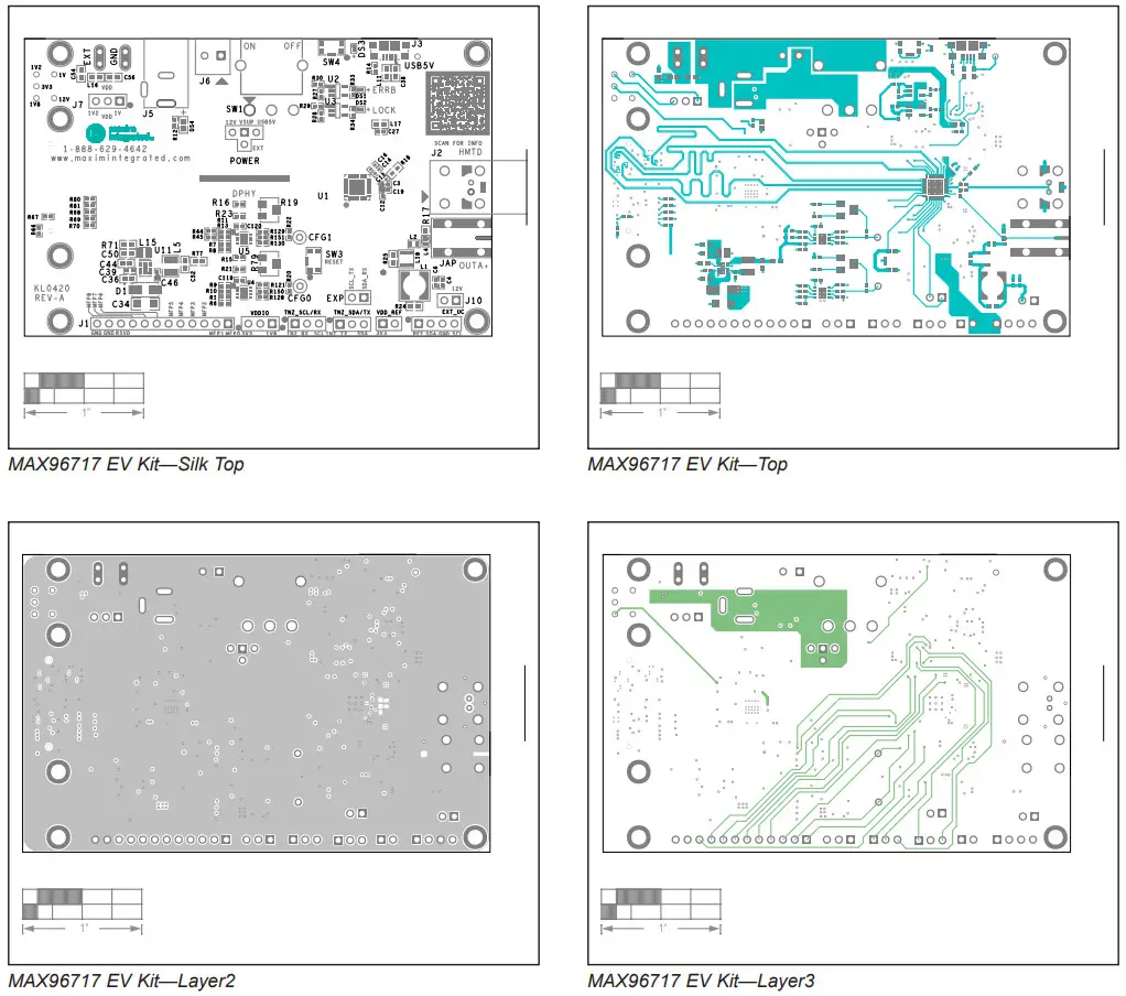
MAX96717 EV Kit Layout


Revision History
| REVISION NUMBER | REVISION DATE | DESCRIPTION | PAGES CHANGED |
| 0 | 9/22 | Initial release | — |
| 1 | 9/22 | Indicating future product use in the Ordering Information table for MAX96717/K/R. | 7 |
| 2 | 9/22 | Updated part numbers in header | All |
![]()
nformation furnished by Analog Devices is believed to be accurate and reliable. However, no responsibility is assumed by Analog Devices for its use, nor for any infringements of patents or other rights of third parties that may result from its use.Specifications subject to change without notice. No license is granted by implication or otherwise under any patent or patent rights of Analog Devices. Trademarks and registered trademarks are the property of their respective owners.
www.analog.com
Mouser Electronics
Authorized Distributor
Click to View Pricing, Inventory, Delivery & Lifecycle Information:
Maxim Integrated:
MAX96717-AAK-EVK# MAX96717-ACK-EVK# MAX96717F-ACK-EVK#
Windows is a registered trademark and registered service mark of Microsoft Corporation.
319-100949; Rev 2; 9/22
© 2022 Analog Devices, Inc. All rights reserved.
Trademarks and registered trademarks are the property of their respective owners.
One Analog Way, Wilmington, MA 01887 U.S.A.
Tel: 781.329.4700
© 2022 Analog Devices, Inc.
All rights reserved.