Contents
algodue ELETTRONICA UEC1P5, UEM1P5 Energy Meter

Product Information
| Name | Model | COM Port | Nominal Voltage, Frequency (Un, f) | PULSE | Ext. Module | M-BUS | RS485 MODBUS | ETHERNET | Preset Packages |
|---|---|---|---|---|---|---|---|---|---|
| UEC1P5-D | UEC1P5-D | PULSE | 3×230/400…3×240/415 V, 50/60 Hz | 2 | 1 | 1 | 1 | – | MID: MID certified meter, with reset function only on partial counters. MID S*: MID certified meter, with reset function only on partial counters, without reactive energy counters on display. NO MID: Meter without MID certification, with reset function only on partial counters. RESET: Meter without MID certification, with RESET function on ALL counters. |
| UEM1P5-D | UEM1P5-D | PULSE | 3×230/400…3×240/415 V, 50/60 Hz | – | 1 | 1 | 1 | – | MID: MID certified meter, with reset function only on partial counters. MID S*: MID certified meter, with reset function only on partial counters, without reactive energy counters on display. NO MID: Meter without MID certification, with reset function only on partial counters. RESET: Meter without MID certification, with RESET function on ALL counters. |
| UEM1P5-4D | UEM1P5-4D | PULSE | 3×230/400…3×240/415 V, 50/60 Hz | – | 1 | 1 | 1 | – | MID: MID certified meter, with reset function only on partial counters. MID S*: MID certified meter, with reset function only on partial counters, without reactive energy counters on display. NO MID: Meter without MID certification, with reset function only on partial counters. RESET: Meter without MID certification, with RESET function on ALL counters. |
| UEM1P5-4D | UEM1P5-4D | PULSE | 3×230/400…3×240/415 V, 50/60 Hz | – | 1 | 1 | 1 | – | MID: MID certified meter, with reset function only on partial counters. MID S*: MID certified meter, with reset function only on partial counters, without reactive energy counters on display. NO MID: Meter without MID certification, with reset function only on partial counters. RESET: Meter without MID certification, with RESET function on ALL counters. |
The communication protocols and the relevant softwares are available at www.algodue.com
WARNING: Device installation, wiring configuration and terminal cover sealing must be carried out only by qualified professional staff. Switch off the voltage before device installation.
AVAILABLE MODELS
| Name | Model | COM port | Nominal voltage, frequency | Available wirings | Tariff input | S0
outputs |
||
| (Un, f) | 3.4.3 | 3.3.3 | 3.3.2 | |||||
| UEC1P5-D | PULSE | Ext.module |
3×230/400…3×240/415 V, 50/60 Hz |
• | • | • | • | 2 |
| UEM1P5-D M | M-BUS | M-Bus | • | • | • | • |
1 |
|
| UEM1P5-4D R | RS485 MODBUS | RS485 | • |
|
• |
1 |
||
| UEM1P5-4D E | ETHERNET | Ethernet | • |
|
1 | |||
For each model the following preset packages are available.
- MID: MID certified meter, with reset function only on partial counters.
- MID S*: MID certified meter, with reset function only on partial counters, without reactive energy counters on display.
- NO MID: Meter without MID certification, with reset function only on partial counters.
- RESET: Meter without MID certification, with RESET function on ALL counters.
For MID S configuration, the device name changes: the S letter is added (e.g. UEM1P5-4DS R).
OVERVIEW
Refer to picture B
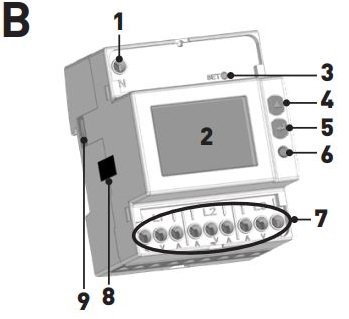
- Neutral terminal
- Backlight LCD display
- SET key
- UP key
- ENTER key
- Metrological LED
- Current and voltage terminals
- Safety-sealing (DO NOT REMOVE)
- Optical port for external communication module – usable only on PULSE model
- The safety-sealing and the sealable terminal covers are included only with MID or MID S package.
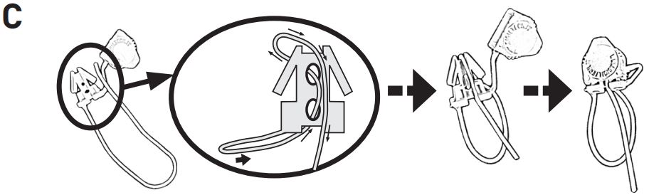
- For a correct seal closure, refer to picture C.
SYMBOLS ON FRONT PANEL (EXAMPLE)
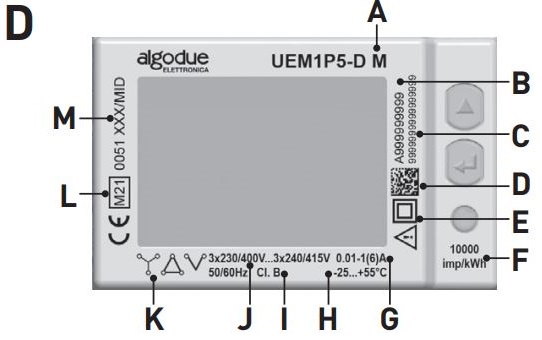
- A. Device name
- B. Serial number
- C. Secondary address for M-BUS model. For PULSE/RS485 MODBUS model: field empty. For ETHERNET model: MAC address
- D. Data Matrix
- E. Protection class
- F. Meter constant (metrological LED)
- G. Base current (max current)
- H. Working temperature
- I. Accuracy class
- J. Nominal voltage/frequency
- K. Wiring type:
 =3phases 4wires 3CTs,
  =3phases 3wires 3CTs,
  =3phases 3wires 2CTs
 - L. MID approval symbols
- M. Type approval certification
If the device is NO MID version, “Cl.1 EN 62053-21” will be shown instead of I, L and M fields.
OPTICAL PORT
OPTICAL PORT: to be combined with external communication modules only
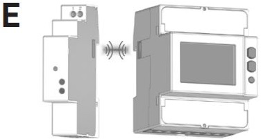
- The optical port is usable according to the device model.
- The optical port works only with a communication module of the same energy meter serie.
- The optical port ensures different communication types with the energy meter, according to the combined communication module. After making communication module connections, combine the energy meter with the module: place them side by side, perfectly lined up, with module optical port facing the meter optical port. Refer to picture E.
RS485 PORT
- The RS485 port is available according to the device model.
- The RS485 port allows to manage the device by MODBUS RTU/ASCII protocol. For device network connection, install a terminal resistance (RT=120…150 Ω) on the RS485 converter side and another one on the last device connected on the line.
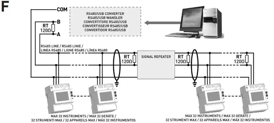
- The maximum recommended distance for a connection is 1200m at 9600 bps. For longer distances, lower communication speed (bps), low-attenuation cables or signal repeaters are needed. Refer to picture F. Default values: MODBUS RTU (8N1), 19200 bps
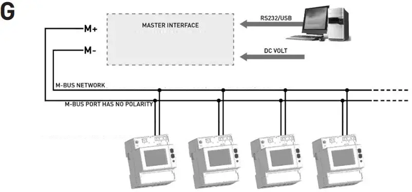
M-BUS PORT
The M-BUS port is available according to the device model. The M-BUS port allows to manage the device by M-BUS protocol. A master interface is required between PC and the M-Bus network to adapt RS232/USB port to network. The maximum number of devices to be connected can change according to the used master interface. For the connection among the different devices, use a cable with a twisted pair and a third wire. Refer to picture G. The device can communicate when at least 2 voltage phases are connected. Default values as defined in EN 13757 standard.
ETHERNET PORT
The ETHERNET port is available according to the device model. Install the included ferrite on the Ethernet cable at a maximum 5 cm distance from the device. Make sure that the Ethernet cable is rolled twice inside the ferrite. The ETHERNET port gives the possibility to manage the device by any PC connected on the Ethernet/Internet network. In the browser web address field type 192.168.1.249, the device Web server will be displayed. The web server has been designed for two user type, Administrator for full device access (username: admin, password: admin), and User for limited device access (username: user, password: user).
Refer to picture H:
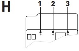
- STATUS LED: communication status; SLOW BLINKING=internal communication ok, ON=switching on or upgrading in progress, FAST BLINKING=internal communication error
- SPD LED: communication speed; OFF=10 Mbps, ON=100 Mbps
- LINK LED: link activity; ON=link ok, BLINKING=link activity
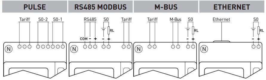
TARIFF INPUT
The tariff input is available according to the device model. The tariff management is carried out by connecting an external device to tariff input, which is providing a signal to the energy counter. The tariff signal is managed as follows:
- if the tariff input detects a voltage free signal (0 V), the device will increase the tariff 1 counters group
- if the tariff input detects a voltage signal (see Technical features), the device will increase the tariff 2 counters group
Note: Total counters increase continuously regardless from the tariff input status.
WIRING DIAGRAMS
It is suggested to install a low power switch or some fuses on the voltage inputs for protection and in order to operate on the instrument without deactivating the plant.
Refer to picture I
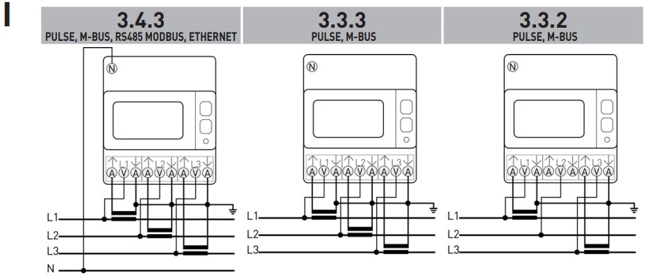
- 3.4.3 = 3 phases, 4 wires, 3 CTs. Available for all models.
- 3.3.3 = 3 phases, 3 wires, 3 CTs. Available only for PULSE and M-BUS models.
- 3.3.2 = 3 phases, 3 wires, 2 CTs. Available only for PULSE and M-BUS models.
Before instrument power ON, check if all connections are made in a proper way. Make sure that the voltage and current terminals are connected correctly. Moreover, make sure that low voltage ports, such as communication ports and/or SO ports, are connected to low voltage lines. These safety precautions may reduce the risk to damage the instrument in case of improper connections.
SYMBOLS ON DISPLAY
Refer to picture J
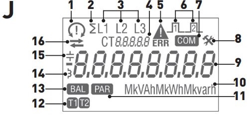
- Phase sequence:
 = correct (123),
  = wrong (132),
  = not defined (e.g. one or more phases are missing)
 - System value
- Value phase number
- Different meanings according to the shown item: · CT XXXX: CT ratio value; SEC: secondary value shown in the main area; SEtUP: Setup page; InFO: Info page
- Metrological parameters corrupted (Code: XX). Useless counter, to be returned to the Manufacturer
- S0-1/S0-2 output active status
- Communication active status
- Setup page
- Main area
- Measuring unit area
- Partial counter value. Flashing=stopped counter
- 1 or 2 tariff counter value
- Balance counter value
- Inductive value
- Capacitive value
- Imported (
 ), exported (
 ) energy or power value
MEASUREMENTS
The parameters are available according to the device model.
| SYMBOL | MEASURE UNIT | DISPLAY | PORT | |
| INSTANTANEOUS VALUES | ||||
| Voltage | V∑, V1, V2, V3 | V | ||
| Line voltage | V12, V23, V31 | V | ||
| Current | I∑, I1, I2, I3, IN | A |  |
|
| Power factor | PF∑, PF1, PF2, PF3 | – | ||
| Apparent power | S∑, S1, S2, S3 | VA | |
|
| Active power | P∑, P1, P2, P3 | W | |
|
| Reactive power | Q∑, Q1, Q2, Q3 | var | |
|
| Frequency | f | Hz | ||
| Phase sequence | CW / CCW | – | ||
| Power direction | D | – | ||
| RECORDED DATA | ||||
| Total active energy | ∑, L1, L2, L3 | Wh | |
|
| Total ind. and cap. reactive energy | ∑, L1, L2, L3 | varh | |
|
| Total ind. and cap. apparent energy | ∑, L1, L2, L3 | VAh | |
|
| Tariff 1-2 energy counters (NO ETHERNET model) | T1 T2 ∑, L1, L2, L3 | Wh, varh, VAh | |
|
| Resettable partial energy counters | PAR ∑ | Wh, varh, VAh | |
|
| Energy balance | BAL ∑ | Wh, varh, VAh | |
|
| In case of ETHERNET model, all parameters can be recorded. | ||||
| OTHER INFORMATION | SYMBOL | STATUS | DISPLAY | PORT |
| Present tariff (NO ETHERNET model) | T1, T2 | – | ||
| Secondary values | SEC | – | ||
| CT ratio | CT | – | ||
| Undervoltage/overvoltage | AL | – | ||
| Undercurrent/overcurrent | AL | – | ||
| Frequency out of range | AL | – | ||
| Partial counter status |  |
Started / Stopped | ||
| S0-1, S0-2 output status |  |
Active | ||
| Legend:
|
||||
The measuring unit can be displayed with k (kilo) or M (Mega) multiplier. The used multiplier is automatically selected by the counter according to the set CT ratio. All the system counters (WhΣ, varhΣ, VAhΣ) can be associated to S0 output. In case of 2 S0 outputs (PULSE model), it is not allowed to set the same counter for both outputs.
NOTE: in case of 3 wire connection, phase-neutral voltages, neutral current, phase powers, phase power factors parameters and all phase counters are not available.
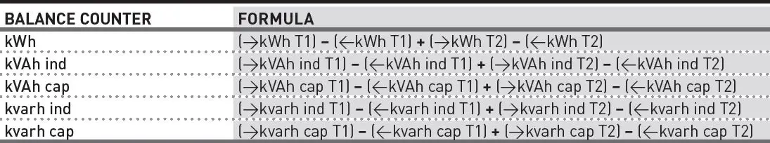
BALANCE COUNTER VALUES CALCULATION
KEY FUNCTIONS
Some functions are available according to the device package.
| HOW TO | WHERE | KEY | PRESS TIME |
| Scroll loops | Any page except for Setup 1/2 | Instantaneous | |
| Scroll pages in a loop | Any loops page | Instantaneous | |
| Display secondary value for 10 s | Any energy counter page | ›3 s | |
| Access Setup 1 pages | “Setup?” page | ›3 s | |
| Access Setup 2 pages | Any page except for Setup 1 | SET | ›3 s |
| Change a value/digit | Setup 1/2 pages | Instantaneous | |
| Confirm a value/digit | Setup 1/2 pages | Instantaneous | |
| Change counter to be reset | Reset page in Setup 2 | Continuous | |
| Exit Setup 1/2 pages | Setup 1/2 pages | ›3 s | |
| Start/stop the displayed partial counter | Partial counters pages | Instantaneous | |
| Reset the displayed partial counter value | Partial counters pages | ›3 s | |
| Display test | Any page except for Setup 1/2 | ›10 s |
PAGE STRUCTURE
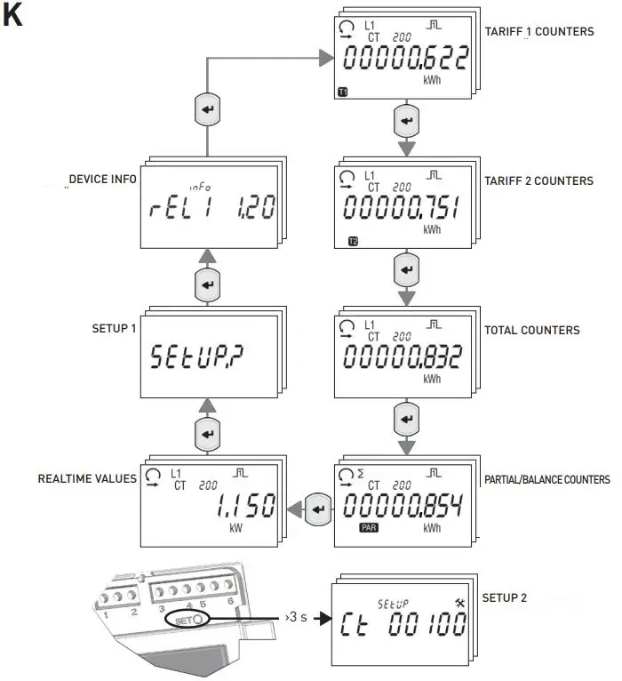
- loops can be displayed (refer to picture K). Some loops can be unavailable according to the device model.
- Press
 to scroll pages in a loop.
NOTE: in case of 3 wire connection, pages showing phase values are not available. For MID S package, reactive energy counters are not displayed.
HOW TO DISPLAY THE COUNTER SECONDARY VALUE
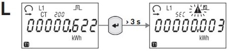
- Feature available only on counter pages.
- By pressing
 key for 3 s, CT secondary measurements will be shown on display (refer to picture L). To scroll energy values, refer to section “PAGE STRUCTURE“. After 10 s keyboard idle, the counter will shown again CT primary data.
HOW TO START / STOP / RESET PARTIAL COUNTERS
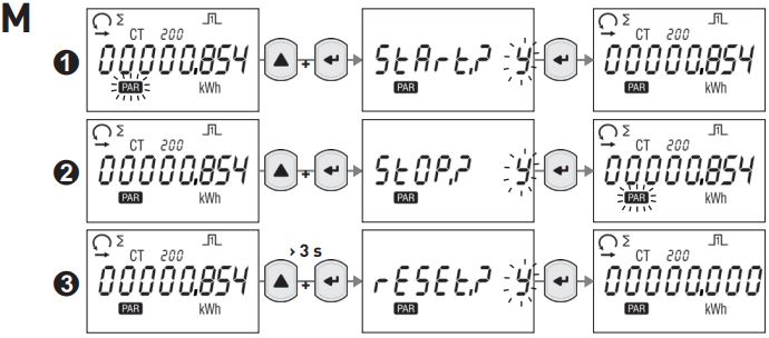
Feature available only on partial counter pages.
To start, stop or reset a partial counter, refer to the following procedures shown in picture M:
- Procedure to start the displayed partial counter
- Procedure to stop the displayed partial counter previously started
- Procedure to reset the displayed partial counter
In START?, STOP?, RESET? pages, selectable items are: Y=to confirm, N=to cancel. To change item, press![]() .
.
SETUP PAGES
SETUP PAGES (pictures N, O)
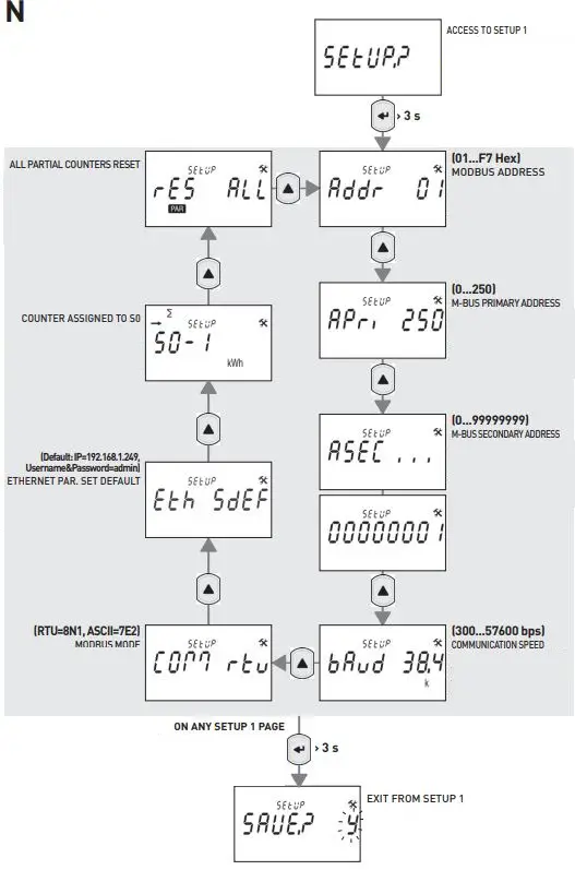
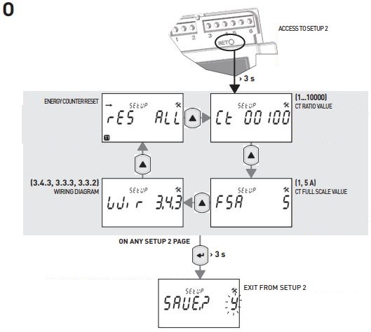
Some setup pages can be unavailable according to the device model/package.
From any setup value page:
- Press, the digit/item will start to flash.
- Press to change the value and confirm with (repeat this procedure for the next digits, if any).
From partial counter reset or set default page:
- Press, a new page for confirmation will be displayed.
- Press to change the flashing value, Y to confirm the reset, N to cancel. Confirm with.
From energy counter reset page (only package RESET):
ALL or 001…120 range are the possible selections:
- ALL=allows to reset all values relevant to a specific counter group. Each counter group can be identified by symbols on display (/, T1/T2).
- 001…120=allows to reset the value relevant to a single counter. Each counter can be identified by symbols on display (</>, L1/L2/L3, T1/T2, measure unit,
 ).
).
The first six pages are relevant to counter groups (ALL) and displayed according to the following order: tariff 1 imported energy / tariff 1 exported energy / tariff 2 imported energy / tariff 2 exported energy / total imported energy / total exported energy The next pages are relevant to single counters (001…120).
NOTE: in case of 3 wire connection, the phase values are not available. For this reason, the counters to be reset within 001…120 range are 30 only.
- To select the group or the energy counter to be reset, press, the value will start to flash.
- Press to change the value. To scroll the value quickly, keep pressed.
- Confirm with , a new page for confirmation will be displayed.
- Press to change the flashing value, Y to confirm the reset, N to cancel. Confirm with.
From setup exit page:
- Press to change the flashing value, Y to exit and save the settings, N to exit without saving, C to continue scrolling setup pages. Confirm with…
INFO PAGES
Up to 7 pages can be displayed to show details about:
- Metrological part firmware release (rel1)
- User interface firmware release (rel2)
- Metrological part checksum (CS1)
- User interface checksum (CS2)
- Communication type
- CT secondary full scale value (FSA)
- Set wiring mode (only PULSE/M-BUS model)
The fifth page is not displayed in case of PULSE model not combined with communication module.
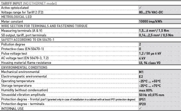
TECHNICAL FEATURES
The technical features can change according to the device model.

CONTACT
Algodue Elettronica Srl
- Via P. Gobetti, 16/F • 28014 Maggiora (NO), ITALY
- Tel. +39 0322 89864
- www.algodue.com
- [email protected]