Contents
AIRGREAN H150 UltraSonic Humidifier

READ AND SAVE THESE INSTRUCTIONS
Thank you for choosing this AIRGREAN humidifier. We at AIRGREAN ENTERPRISE truly appreciate your business. This manual is intended to be a source of information on how to operate, maintain and troubleshoot your new humidifier.
Please take the time to read through this manual thoroughly.
Product Description
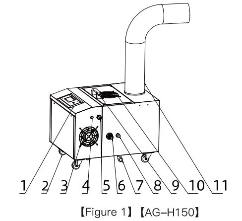
- Control panel
- Universal wheel
- Radiator fan
- Humidity sensor connector
- Power supply (10a grounding plug)
- Water inlet (1/2) external thread
- Water outlet (1/2) internal thread
- Overflow (1/2) external thread
- Handle
- Fog blowing fan
- Mist outlet
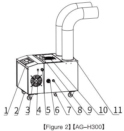
- Control panel
- Universal wheel
- Radiator fan
- Humidity sensor connector
- Power supply (10a grounding plug)
- Water inlet (1/2) external thread
- Water outlet (1/2) internal thread
- Overflow (1/2) external thread
- Handle
- Fog blowing fan
- Mist outlet
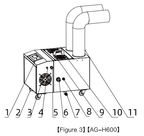
- Control panel
- Universal wheel
- Radiator fan
- Humidity sensor connector
- Power supply (10a grounding plug)
- Water inlet (1/2) external thread
- Water outlet (1/2) internal thread
- Overflow (1/2) external thread
- Handle
- Fog blowing fan
- Mist outlet
Filter installation
Filter bracket
- Using thesupplied screws, attached the filter underneath the bracket (See Fig. 4)
- Attach bracket to the pre-drilled holes located on the backside of the unit(See Fig. 5)
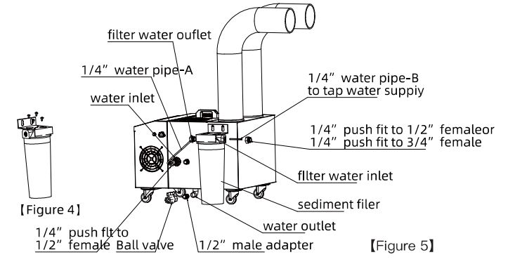
Filter connections
Attach hose connectors onto the end of each hose.
- PIPE-A: Connect one end to the filter 1/4″ hose and the other end to the water inlet port on the unit. (See Fig. 5)
- PIPE-B: Connect one end to the filter 1/4″ hose and the other end to the fresh water supply.
Pipe installation
In order to avoid dripping on the ground, the fog outlet noles must be pointing upwards at a minimum of 30 degrees.
Height at the end of the pipe needs to be higher than the humidifying section, 1/8 + rise per foot. (See Fig. 6).
DO NOT connect the water pipe with a “trap”. (See Fig. 7).
To have the best result, outlet pipe connections should be no shorter than 18″ before an elbow connection. (See Fig. 8)
Note: The direction of the fog outlet can not be towards the top of the fan.

Note: When in use, the water level of the sewer drain should be lower than the position of the machine drain(See Fig. 9).
Before using, remove the plug and install the ball valve (spare parts are free)

Control panel

Button description(Fig. 10)
- Power switch: press the “POWER” button to start or stop unit.
- Connect the power supply, connect the humidity sensor, the display shows the current environmental humidity.
- When the “Humidity” flashes in the running state, it indicates that the current ambient humidity is higher than the set point, and it is in the standby state;
When the ambient humidity is lower than the set point, the device will automatically restart
Timer
- Timer to start: Press “SET” button enter the timing setting,when “time start up” flashes, press “+” or “-” buttons to set timer range between 1 to 24 hours.
- Timer to stop: Press “SETTING” two times, enter timing shutdown setting. The “timed startup” flashes, press “+”or “_”to set timer stop working.
Humidity
Press “+” or “-” buttons to adjust humidity between 10-90% range.
System function operation
- Automatic control: When the ambient humidity reaches the set point, it will automatically stop running, the fan will delay 30s.
When the current ambient humidity is lower than the set point, automatically restart, the set humidity range is adjustable from 10-95%. - Low water level warning: When the system detects the water level is lower than the warning level, the unit will stop automatically.
- Special note:Water level should be 3mm-12mm higher than the atomizer. Too low water level will affect the fogging situation. (Note: In order to prevent the float shift during shipping, suggest open water tank to check whether the float position is correct)
Technical Parameters
|
Model |
Power Supply | Power
Watts |
Spray Capacity
pint/hour |
Way to control | Outlet diameter
(Inches) |
Dimensions (Inches) |
N.W. (lbs) |
| AG-Hl50 | 110V- 60Hz | 235 | 6.2 |
Automatic |
4.33 singl e outlet |
20.04′,.l 5.l 6′,.l 2.05″ |
38.1 |
| AG-H300 | l 10V-6 0Hz |
330 |
12.5 |
Automatic |
4.33 double outlet |
20.04′,. l 5.l 6′,. l 2.05″ |
40.5 |
| AG-H600 |
l 10V-6 0Hz |
665 |
25 |
Automatic |
4.33 double outlet |
20.04′,. l 5.l 6′,.l 2.05″ |
50.7 |
Error codes
| Code | Meaning | Processing method |
|
E2 |
The humidity sensor is faulty or not connected |
Replace the humidity sensor or connect the sensor |
|
E3 |
The temperature sensor is faulty or not connected |
Replace the temperature sensor or connect the sensor |
Troubleshooting guide
| Problem | Possible causes | Solution |
|
Device is not running |
A. No power supply B. The fuse is blown C. Power switch is off D. Humidity has reached the set requirement |
A. Check power supply and restore power supply B. Replace the fuse of the same specification C. Turn on the power switch |
|
The supply tank is not filling with water |
A. No water fr om the pipe B. The water inlet float is blocked |
A. Check the water supply pipeline B. Cleaning the magazine of the float hole position |
|
Equipment does not stop water |
A. The flo ating ball is displaced B. The float has foreign matter C. Damage to the float |
A. Adjust the correct position B. Remove foreign objects C. Replace the float |
|
The fog lamp does not light up |
A. The floating ball is displaced B. The fl oat has foreign matter C. Damage to the float |
A. Ad just the correct position B. Remove foreign objects C. Replace the fl oat |
|
Water overflows from the cabinet |
A. Leaking water tank B. The fog is poured back and the blower outlet overflows |
A. Repair or replace the water tank B. Check the fan port |
|
A. Too much scale inside the |
A. Cleaning the water tank and atomizing chip
B. Replace the atom izing chip C. Maintain normal voltage D. Adjust the water level E. Clean the water tank and pipeline |
|
| water tank | ||
| B. Atom ized presbyopia | ||
| Reduced or no spray | C. Voltage reduction
D. The water level of the water |
|
| tank is too high or too low | ||
| E. There are oily substances in | ||
| water | ||
|
The mist has an odor |
A. There are other substances in the pipeline or water tank |
A. Clean the unit |
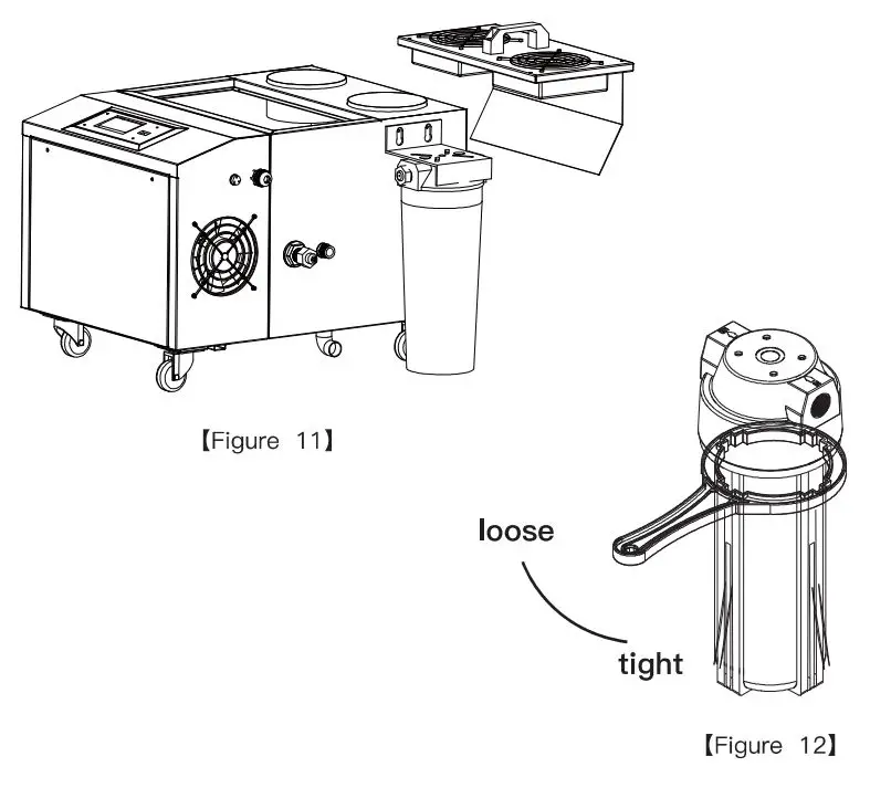
Care and maintenance
Clean the filter:
The filter should be cleaned regularly, at least once a month.
- Unscrew the cover of the filter with the wrench included. (See Fig.11)
- Clear the dirt on the filter element.
- Re-install the cover.
- The filter should be replaced every 3-6 months.
Limited warranty
- The warranty period is one year for the general machine. This warranty applies to repair or replacement of product found to be defective in materials or workmanship. This warranty does not apply to damage resulting from unusual wear, abusive, unreasonable use or supplemental damage. This warranty does not cover damage from unauthorized repairs or from any use not in accordance with the instruction manual.
Defects that are the result of normal wear and tear will not be considered manufacturing defects under this warranty. - Filter and filter element are consumable material and is not covered by the warranty.