![]()
BD3-6KTL-RL1 Single-Phase Hybrid Solar Inverter
User Manual
BD Series
Hybrid Inverter User Manual
Contents
Introduction
1.1 Important Safety Instructions
Danger!
- Danger to life due to high voltages in the inverter!
- All work must be carried out by qualified electrician.
- The appliance is not to be used by children or persons with reduced physical sensory or mental capabilities, or lack of experience and knowledge, unless they have been given supervision or instruction.
- Children should be supervised to ensure that they do not play with the appliance.
Caution!
- Danger of burn injuries due to hot enclosure parts!
- During operation, the upper lid of the enclosure and the enclosure body may become hot.
- Only touch the lower enclosure lid during operation.
Caution!
- Possible damage to health as a result of the effects of radiation!
- Do not stay closer than 20 cm to inverter for any length of time.
![]() Note!
Note!
- Grounding the PV generator.
- Comply with the local requirements for grounding the PV modules and the PV generator. It is recommends connecting the generator frame and other electrically conductive surfaces in a manner which ensures continuous conduction and ground these in order to have optimal protection of system and persons.
Warning!
Ensure input DC voltage ≤Max. DC voltage .Over voltage may cause permanent damage to inverter or other losses, which will not be included in warranty!
Warning!
- Authorized service personnel must disconnect both AC and DC power from inverter before attempting any maintenance or cleaning or working on any circuits connected to inverter.
- Risk of electric shock!
- Accessories only together with the inverter shipment are recommended here.Other wise may result in a risk of fire, electric shock, or injury to person.
- Make sure that existing wiring is in good condition and that wire is not undersized.
- Do not disassemble any parts of inverter which are not mentioned in installation guide. It contains no user-serviceable parts. See Warranty for instructions on obtaining service. Attempting to service the inverter yourself may result in a risk of electric shock or fire and will void your warranty.
- Keep away from flammable, explosive materials to avoid fire disaster.
- The installation place should be away from humid or corrosive substance.
- Authorized service personnel must use insulated tools when installing or working with this equipment.
- PV modules shall have an IEC 61730 class A rating.
- Never touch either the positive or negative pole of PV connecting device. Strictly prohibit touching both of them at the same time.
- The unit contains capacitors that remain charged to a potentially lethal voltage after the MAINS , battery and PV supply has been disconnected.
- Hazardous voltage will present for up to 5 minutes after disconnection from power supply.
- CAUTION-RISK of electric shock from energy stored in capacitor, Never operate on the inverter couplers, the MAINS cables, Battery cables, PV cables or the PV generator when power is applied. After switching off the PV , battery and Mains, always wait for 5minutes to let the intermediate circuit capacitors discharge before unplugging DC , battery in plug and MAINS couplers.
- When accessing the internal circuit of inverter, it is very important to wait 5 minutes before operating the power circuit or demounting the electrolyte capacitors inside the device. Do not open the device before hand since the capacitors require time sufficiently discharge!
1.2 Explanation of Symbol
This section gives an explanation of all the symbols shown on the inverter and on the type label.
- Symbols on the Type Label
| Symbol | Explanation |
| CE mark. The inverter complies with the requirements of the applicable CE guidelines. |
|
| TUV certified. | |
| RCM remark. | |
| SAA certification. | |
| Beware of hot surface. The inverter can become hot during operation. Avoid contact during operation. |
|
| Danger of high voltages. Danger to life due to high voltages in the inverter! |
|
| Danger. Risk of electric shock! |
|
| Observe enclosed documentation. | |
| The inverter can not be disposed together with the household waste. Disposal information can be found in the enclosed documentation. | |
| Do not operate this inverter until it is isolated from battery, mains and on-site PV generation suppliers. | |
| Danger to life due to high voltage. There is residual voltage existing in the inverter after powering off, which needs 5 min to discharge. • Wait 5 min before you open the upper lid or the DC lid. |
1.3 Basic features
BD series hybrid inverter is a high quality inverter which can convert solar energy to AC energy and store energy into battery.
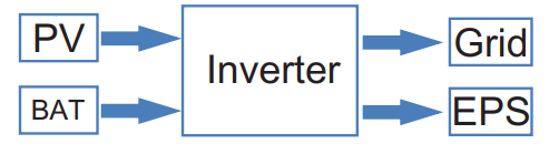
The inverter can be used to optimize self consumption, store in the battery for future use or feeding to public grid. Work mode depends on PV energy and user’ s preference. It can provide power for emergency use during the grid lost by using t h e energy from battery an d in verger (generated from PV).In addition, the parallel function is available(off grid model).
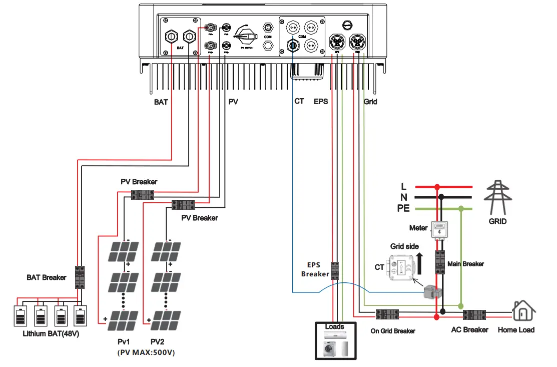
System Diagram 1 (applies to most countries )
System Diagram 2 (applies to wiring rules AS/NZS_3000:2012 for Australia and New Zealand )
![]() Note!
Note!
The instrument and switch in the above figure are provided by users.
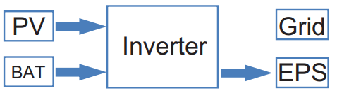
1.4 Work Modes
Hybrid Inverter provides multiple work modes based on different requirements.
Work modes: Self-use
 |
1.When PV, Grid, Battery is available: A. Solar energy provides power to the loads as first priority, if solar energy is sufficient to power all connected loads, solar energy excess power will provides to charge battery, and then redundant power will feed to grid. |
 |
B. Solar energy provides power to the loads as first priority ,if solar energy is not sufficient to power all connected loads, battery energy will supply power to the loads at the same time. |
 |
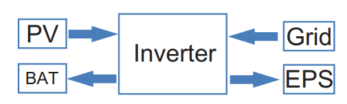
C. Solar energy provides power to the loads as first priority ,if solar energy and battery are not sufficient to power all connected loads, utility energy (Main Grid) will supply power to the loads with solar energy at the same time. |
 |
2 .When PV, Grid is available(without battery): A. Solar energy provides power to the loads as first priority ,if solar energy is sufficient, the excess power will feed to grid. |
|
B. Solar energy provides power to the loads as first priority, if solar energy is not sufficient to power all connected loads, Grid energy will supply power to the loads at the same time. |
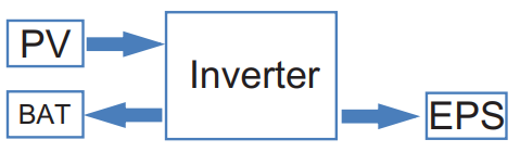 |
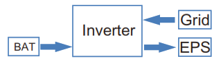
3 .When PV, Battery is available Grid is disconnected): A. Solar energy provides power to the loads as first priority ,if solar energy is sufficient to power all connected loads, solar energy will provides to charge battery. |
|
B. Solar energy provides power to the loads as first priority ,if solar energy is not sufficient to power all connected loads, battery energy and solar energy will supply power to the loads at the same time. |
Work modes: Peak shift
 |
1.When PV, Grid, Battery is available: A. On charge time, solar energy will charge battery as first priority. The excess energy will supply power to the loads. If solar energy is sufficient to supply loads and charge battery, and If there’s still some extra energy, then the excess power will feed the power to grid |
 |
B. On charge time, solar energy will charge battery as first priority. Then the excess solar energy will supply power to loads. If solar energy is not sufficient to charge battery and supply loads, grid will supply all the connected loads with solar energy together. |
 |
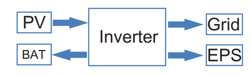
C. On discharge time, solar energy provides power to the loads as first priority, if solar energy is sufficient to supply loads ,and if there’s still some extra energy from solar energy ,then the excess power and battery will deliver the power to the grid at the same time. |
|
D. In the period of no charge or discharge, the solar power supply loads at first priority , excess energy to the grid. |
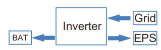 |
2. When Grid, Battery is available(PV is disconnected): A. On charge time, grid will charge battery and supply power to the connected loads at the same time. |
 |
B. On discharge time, if load power is less than battery power, battery will supply power to loads as first priority, the excess power will be feed to grid. |
 |
C. On discharge time, if load power is more than battery power, battery and grid will supply power to the loads at the same time. |
Work modes: Bat priority
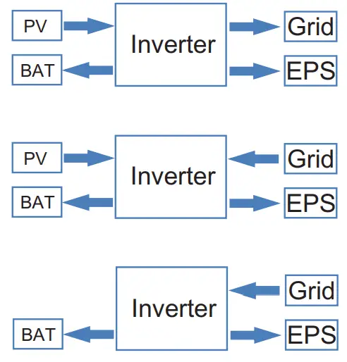 |
1. When PV, Grid, Battery is available: A. Solar energy will charge battery as first priority, if solar energy is excess, the excess power will supply load. If there’s still some extra energy, then the excess power will feed the power to grid . B. Solar energy will charge battery as first priority, if solar energy is excess, the excess power will supply load. If solar energy is not sufficient to charge battery and supply loads, grid will supply power to loads. 2. When Grid, Battery is available(PV is disconnected): Grid will supply power to load and charge battery at the same time. |
![]() Note!
Note!
If set anti-Reverse function allowable, Once on the work mode of Self-use Peak , shift, battery priority, the system will not feed power to grid.
1.5 Dimension
Interface definition and Technical Data
2.1 Interface definition
| Object | Description |
| A/B | Battery +/Battery – |
| C/D | PV1+/PV1- |
| J/K | PV2+/PV2- |
| E | DC switch |
| F | WiFi port for external WiFi |
| L | Reserved port |
| G | DRM/BMS |
| H | Grid current / DRY IO |
| M | USB port for upgrading |
| N | POWER CAN /LEAD-NTC |
| I | Pressure valve |
| O | EPS output |
| P | Grid output |
![]() Note!
Note!
- The Update port: For on-premises upgrades.
- The BMS port: BMS communication for lithium batteries.
- The CT port: For external grid side CT to detect current size.
- The DRM port, CAN port, NTC port and DRY IO port: Reserved port, temporarily unavailable
2.2 Technical Data
| Model | BD3KTL-RL1 | BD3K6TL-RL1 | BD4KTL-RL1 | BD4K6TL-RL1 | BD5KTL-RL1 | BD6KTL-RL1 |
|
DC input |
||||||
| Max. recommended DC power [W] | 4600 | 4600 | 6000 | 6000 | 7000 | 7000 |
| Max. DC voltage[V] | 550 | 550 | 550 | 550 | 550 | 550 |
| Nominal DC operating voltage[V] | 360 | 360 | 360 | 360 | 360 | 360 |
| MPPT voltage range [V] | 125-500 | 125-500 | 125-500 | 125-500 | 125-500 | 125-500 |
| MPPT voltage range@full load [V] | 150-500 | 150-500 | 170-500 | 170-500 | 220-500 | 220-500 |
| Max. input current [A] | 14/14 | 14/14 | 14/14 | 14/14 | 14/14 | 14/14 |
| Max. short circuit current [A] | 17.5/17.5 | 17.5/17.5 | 17.5/17.5 | 17.5/17.5 | 17.5/17.5 | 17.5/17.5 |
| Start input voltage [V] | 125 | 125 | 125 | 125 | 125 | 125 |
| No. of MPP trackers | 2 | 2 | 2 | 2 | 2 | 2 |
| Strings per MPP tracker | 1 | 1 | 1 | 1 | 1 | 1 |
| Max. inverter backed current to array | 0 | 0 | 0 | 0 | 0 | 0 |
| DC disconnection stich |
/ |
|||||
|
AC output |
||||||
| Nominal AC power[VA] | 3000 | 3680 | 4000 | 4600 | 5000 | 6000 |
| Max. apparent AC power[VA] | 3000 | 3680 | 4000 | 4600 | 5000 | 6000 |
| Rated grid voltage(range)[V] |
230 (176 to 270) |
|||||
| Rated grid frequency[Hz] |
50/60 |
|||||
| Nominal AC current[A] | 13 | 16 | 17.4 | 20 | 21.7 | 26 |
| Max.AC current[A] | 13 | 16 | 17.4 | 20 | 21.7 | 26 |
| Displacement power factor |
0.99 leading. 0.99 lagging |
|||||
| Total harmonic distortion(THDI) |
< 2% |
|||||
| Load control |
optional |
|||||
| AC input | ||||||
| Nominal AC power[VA] | 3000 | 3680 | 4000 | 4600 | 5000 | 6000 |
| Rated grid voltage(range)[V] |
230(176 to 270) |
|||||
| Rated grid frequency[Hz] |
50/60 |
|||||
| Nominal AC current[A] | 13 | 16 | 17.4 | 20 | 21.7 | 26 |
| Max.AC current[A] | 13 | 16 | 17.4 | 20 | 21.7 | 26 |
| Displacement power factor |
0.99 leading~0.99 lagging |
|||||
| AC inrush current | 35 | 35 | 35 | 35 | 35 | 35 |
|
EPS output |
||||||
| EPS rated power[VA] | 3000 | 3680 | 4000 | 4600 | 5000 | 6000 |
| Max. EPS power[VA] | 3000 | 3680 | 4000 | 4600 | 5000 | 6000 |
| EPS rated voltage, Frequency |
230VAC, 50/60Hz |
|||||
| EPS rated current[A] | 13 | 16 | 17.4 | 20 | 21.7 | 26 |
| Max. EPS current[A] | 13 | 16 | 17.4 | 20 | 21.7 | 26 |
| Switch time[s] |
<20ms |
|||||
| Total harmonic distortion(Th.D.) |
<2% |
|||||
| Parallel operation |
Yes |
|||||
| Compatible with the generator |
Yes(signal provided only) |
|||||
| Battery parameter | ||||||
| Battery type |
Lithium battery/Lead-ACID |
|||||
| Battery voltage range[V] |
40-58 |
|||||
| Recommended battery voltage[V] |
48 |
|||||
| Cut Off Voltage[V] |
40 |
|||||
| Max. charging Voltage[V] |
58 |
|||||
| Max. Protective Voltage[V] |
59 |
|||||
| Max. charge/discharge current[A] | 95/62.5 | 95/76.6 | 95/83.3 |
95/95.8 |
95/104.2 | 95/110 |
| Peak charge/discharge current[A] | 95/62.5 | 95/76.6 | 95/83.3 |
95/95.8 |
95/104.2 | 95/110 |
| Communication interfaces |
CAN/RS485/WIFI/LAN/DRM |
|||||
| Reverse connect protection |
Yes |
|||||
|
Efficiency |
||||||
| MPPT efficiency |
99.9% |
|||||
| Euro efficiency |
97% |
|||||
| Max. efficiency |
97.6% |
|||||
| Max. Battery charge efficiency |
95% |
|||||
| Max. Battery discharge efficiency |
95% |
|||||
Note: If the South African national grid standard is selected, the grid power is only 4.6kW!
2.3 Basic Data
| Model | BD3KTL-RL1 | BD4KTL-RL1 | BD5KTL-RL1 |
| BD3K6TL-RL1 | BD4K6TL-RL1 | BD6KTL-RL1 | |
| Dimension [W/H/D](mm) | 550*520*200 | ||
| Dimension of packing [W/H/D](mm) | 665*635*330 | ||
| Net weight [kg] | 25 | ||
| Gross weight [kg] | 31 | ||
| Installation | modularization | ||
| Operating temperature range[℃] | -25~+60 (derating at 45) | ||
| Storage temperature [℃] | -25~+60 | ||
| Storage/Operation relative humidity | 4%~100% (Condensing) | ||
| Altitude [m] | <2000 | ||
| Ingress Protection | IP65(for outdoor use) | ||
| Protective Class | Ⅰ | ||
| Night-time consumption | <3W | ||
| Over Voltage Category | lb(MAINS),Ⅱ( PV,Battery) | ||
| Pollution Degree | II | ||
| cooling | Natural | ||
| Noise level | <40dB | ||
| Inverter Topology | non-isolated | ||
| Active anti-islanding method | Power variation | ||
| Communication interface | CAN/RS485/WIFI/LAN/DRM | ||
2.4 Safety and Protection
| Safety & Protection | |
| Over/under voltage protection | YES |
| DC isolation protection | YES |
| Monitoring ground fault protection | YES |
| Grid protection | YES |
| DC injection monitoring | YES |
| Back feed current monitoring | YES |
| Residual current detection | YES |
| Anti-islanding protection | YES |
| Over load protection | YES |
| Over heat protection | YES |
| Max. output fault current | 55A |
| Max. output over current | 28.7A |
Installation
3.1 Check for Physical Damage
Make sure the inverter is intact during transportation. If there is any visible damage, such as cracks, please contact your dealer immediately.
3.2 Packing List
Open the package and take out the product, please check the accessories first.
The packing list shown as below.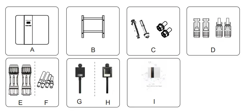
| Object | Description |
| A | Inverter |
| B | Bracket |
| C | Expansion screws and pan-head screws |
| D | PV connectors (2*positive, 2*negative) |
| E | AC terminals |
| F | PV pin connectors (2*positive, 2*negative) |
| G | Wi module (optional) |
| H | GPRS module (optional) |
| I | User manual |
3.3 Tools required for installation.
Installation tools : crimping pliers for binding post and RJ 45, screwdriver, manual wrench etc. 
3.4 Mounting
Space Requirement
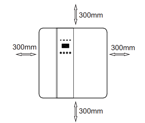 Table Available Space Size
| Position | Man-size |
| Left | 300mm |
| Right | 300mm |
| Top | 300mm |
| Bottom | 300mm |
| Front | 300mm |
Step 1: Screw the wall bracket on the wall
1.1 Place the bracket on the wall and mark down the position of the 4 holes.
1.2 Drill holes with driller, make sure the holes are deep enough (at least 60mm) to support the inverter.
1.3 Install the expansion tubes in the holes, and tighten them. Then install the wall bracket with the expansion screws.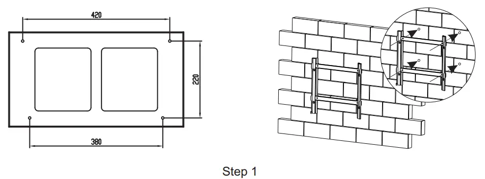
Step 2: Place the inverter on the wall mounted bracket by holding the handle on the side. 
Step 3: Tighten the fixing screws on both sides of the inverter.
Step 4: If necessary, customer can install an anti-theft lock on the left-bottom of the inverter. 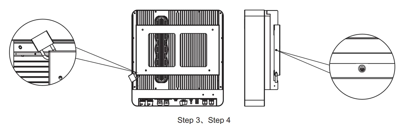
Electrical Connection
- Electrical connection diagram
4.1 Grid connection and EPS connection
Hybrid inverter are designed for single phase grid. Voltage is 220/230/240V, frequency is 50/60Hz.
Other technical requests should comply with the requirement of the local public grid.
Table 1 Cable and Micro-breaker recommended
| Model | BD3KTL-RL1 | BD3K6TL-RL1 | BD4KTL-RL1 | BD4K6TL-RL1 | BD5KTL-RL1 | BD6KTL-RL1 |
| Cable | 4-5 mm² | 5-6mm² | ||||
| Micro-breaker | 20A | 32A | ||||
Micro-breaker should be installed between inverter and grid, any load should not be connected with inverter directly.
Step1. Check the grid voltage.
1.1 Check the grid voltage and compare with the permissive voltage range (Please refer to technical data).
1.2 Disconnect the circuit board from all the phases and secure against re-connection.
Step2. Remove the waterproof lid from the grid port on the inverter. 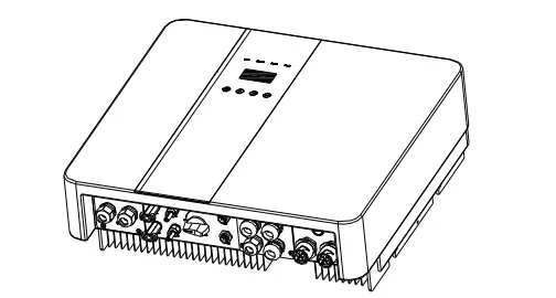
Step3. Make AC and EPS wires.
3.1 Choose the appropriate wire(Cable size: refer to Table 1).
3.2 Reserve about 60mm of conductor material sectional area and remove 10mm of insulation from the end of wire.
3.3 Separate the docking screw cap of the AC terminal from the housing portion and insert stripped wires into AC terminal and tighten the screws with a hexagonal wrench.
3.4 Tighten the docking screw cap and housing portion of the AC terminal.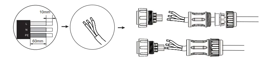
Step4. Connect the AC connector to the GRID port of the inverter and tighten the screw cap . Connect the LOAD connector to the EPS port of the inverter and tighten the screw cap .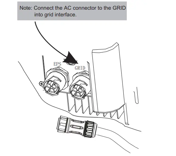
4.2 PV connection
Hybrid Inverter can be connected in series with 2-strings PV modules for 3KW,3.6KW,4KW,4.6KW, 5KW and 6KW.
Select PV modules with excellent function and reliable quality. Open-circuit voltage of module arrays connected in series should be <Max. DC input voltage; operating voltage should be conformed to MPPT voltage range. Max. DC Voltage Limitation
| Model | BD3KTL-RL1 | BD3K6TL-RL1 | BD4KTL-RL1 | BD4K6TL-RL1 | BD5KTL-RL1 | BD6KTL-RL1 |
| Max. DC Voltage (V) | 550 | |||||
| MPPT Voltage Range(V) | 125-500 | |||||
Warning!
- PV module voltage is very high, which already achieve dangerous voltage range, please comply with electric safety rules when connecting.
- Please do not make PV positive or negative ground!
Connection Steps:
Step1. Checking PV module to ensure PV is in open circuit state and ensure the PV+ and PV- ports of the PV string are correct.
Step2. Separating the DC connector.
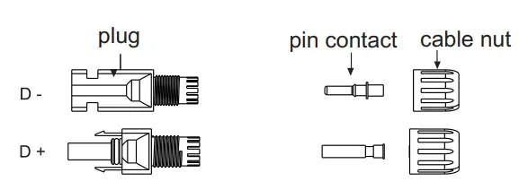 Step3. Wiring
3.1 Choose the 12 AWG wire to connect with the cold-pressed terminal.
3.2 Remove 10mm of insulation from the end of wire.
3.3 Insert the insulation into pin contact and use crimping plier to clamp it.
Step4. Insert pin contact through the cable nut to assemble into back of the male or female plug. When you feel or heard a “click” sound the pin contact assembly is seated correctly. 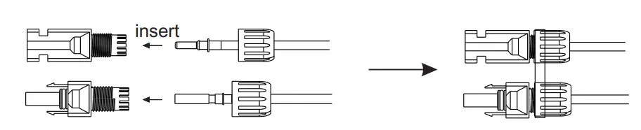
Step5. Plug the PV connector into the corresponding PV connector on inverter.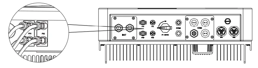
4.3 Battery Connection
Note
- Before choosing battery, please note the maximum voltage of battery can not exceed 59V and the rated voltage of battery can not exceed 48V, and the battery communication should be compatible with Hybrid inverter.
- Before connecting to battey, please install a nonpolarized DC(125A) breaker to make sure inverter can be securely disconnected during maintenance.
- The connecting cable between the battery and the inverter shall be at least 4AWG.
- The battery communication can only work when the battery BMS is compatible with the inverter.
- To replace the battery, you need to turn off all switches and unplug the system communication line.
- All the above wiring and operations must be carried out after the whole machine is powered down, and all of them need professional personnel to complete
Power Connection Steps:
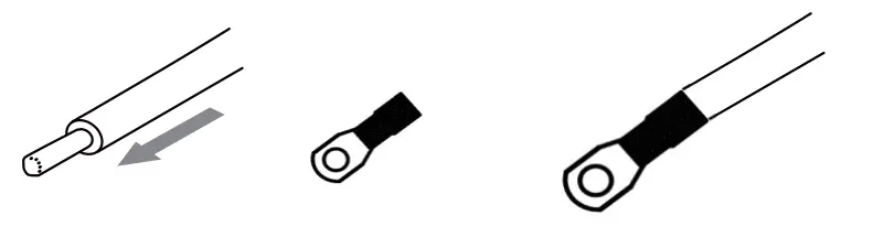
Step1. Choose the 4AWG wire and strip the cable to 15mm.
Step2. Select two O-terminals with an aperture of M6.
Step3. Insert the stripping line into the O-terminal and clamp it with a crimping clamp.
Step1,2,3.
Step4. Remove waterproof cover plate.
Step5. Disassemble the waterproof connector and pass the cable through the waterproof connector. 
Step6. Connect the cable to the terminal of the inverter .
Step7. Assemble waterproof connectors and waterproof covers plate.
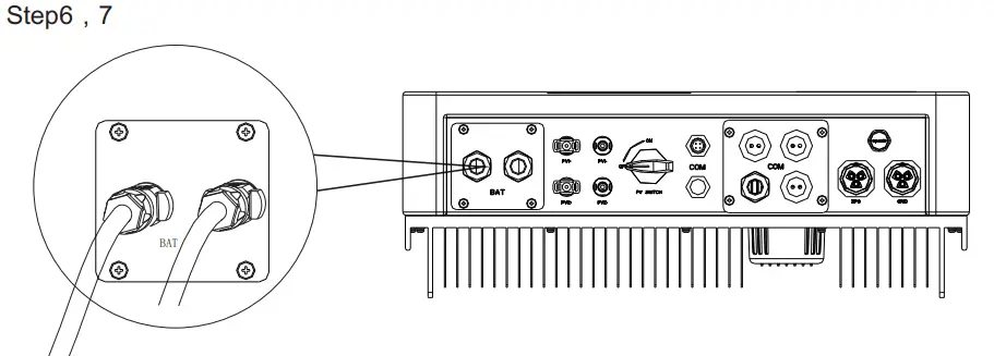
![]() Note!
Note!
Positive and negative lines are not allowed to reverse.
The positive pole on the left and the negative pole on the right.
4.4 Communication interface definition
BMS PIN Definition
Communication interface between inverter and battery is RS485 or CAN with a RJ45 connector.
The wiring sequence of the crystal head conforms to the 568B standard: orange white, orange, green white, blue, blue white, green, brown white and brown.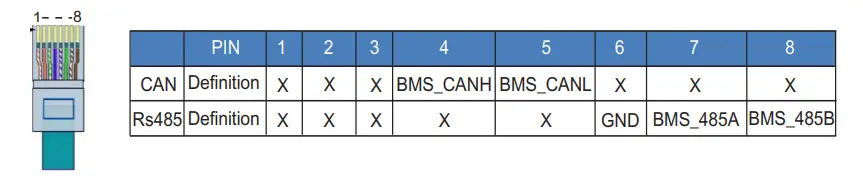
DRY_IO (RJ45 PIN) Definition
Reserved dry contact interface of the inverter. 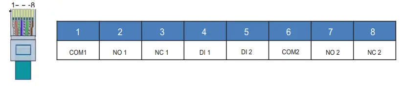
DRM Connection
DRM is provided to support several demand response modes by emitting control signals as below.
Note: Only PIN6(DRM0) is available now, and other PIN functions are being developed.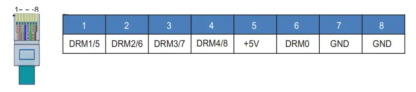
4.5 WiFi And GPRS Connection(optional)
Inverter provides a WiFi port which can collect data from inverter and transmit it to monitoring-website by WiFi.
Step1. Plug Wifi into “COM” port at the bottom of the inverter.
Step2. Build the connection between the inverter and router.
Step3. Create a user account online.( Please check the WiFi user manual for more details).
Diagram

GPRS Connection :
GPRS connection interface is consistent with WIFI interface, Please refer to the GPRS user manual for detailed connection steps.
Diagram
LCD Interface and Setting
5.1 Control Panel
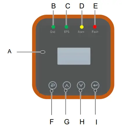
| Object | Name | Description |
| A | LCD Screen | Display the information of the inverter. |
| B | Indicator LED | lit in green: The inverter is in grid mode. Off: The inverter is in not in grid mode. |
| C | lit in green: The inverter is in off-grid mode. Off: The inverter is in not in off-grid mode. | |
| D | lit in Yellow: The inverter is in Warning . Off: The inverter has no Inverter Warning | |
| E | lit in red: The inverter is in fault status. Off: The inverter has no errors. | |
| F | Function Button | Esc: Return from current interface or function. |
| G | Up: Move cursor to upside or increase value. | |
| H | Down: Move cursor to downside or decrease value. | |
| I | Enter: Confirm the selection. |
5.2 Instructions for LED Indicator
| Grid (Green) | EPS (Green) | Alarm (Yellow) | Fault (Red) | |
| Initialization | off | off | off | off |
| Stand-by | off | off | off | off |
| Grid mode | on | off | off | off |
| Off-Grid | off | on | off | off |
| Bypass of mains | off | on | on | off |
| Fault | off | off | off | on |
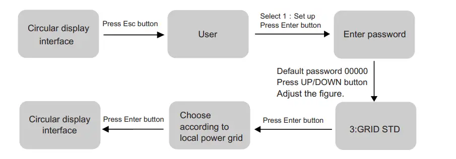
5.3 Instructions for the use of three modes

For example, Before selecting the mode, you can set it up ac cording to the local power grid, PV input mode and battery type.
Power grid:
PV input mode:

Battery parameters:
5.4 LCD Interface
5.4.1 Error information
| Interface | Description |
| Numbers represent error codes and text is error information. Refer to Chapter 9 for specific contents. NOTE: When there is a lock mark in the upper right corner of the screen, you cannot turn the page, you need to press Enter to unlock it first. |
|
| ERROR NO. 02:BatDisconnect |
|
5.4.2 System setting
| Interface | Description |
| GRID VOLT: 0.0V CURR: 0.00A FREQ: 0.00Hz |
VOLT: Gird real-time voltage. CURR: CT real-time current. FREQ: Grid real-time frequency. |
5.4.12 INV
| Interface | Description |
| INV VOLT: 0.0V CURR: 0.00A FREQ: 0.00Hz |
VOLT: INV real-time voltage. CURR: INV real-time current. FREQ: INV real-time frequency. |
5.4.13 LOAD
| Interface | Description |
| LOAD VOLT: 0.0V CURR: 0.00A PERCENT: 0% |
VOLT: LOAD real-time voltage. CURR: LOAD real-time current. PERCENT: LOAD real-time percentage. |
5.4.14 POWER
| Interface | Description |
| POWER INV: 0.0W GRID: 0.0W |
INV: INV power. GRID: Grid power. |
5.4.15 POWER
| Interface | Description |
| POWER PV I/P: 0W LOAD: 0W BAT: 0W |
PV I/P: PV power. LOAD: LOAD power. BAT: BAT power. |
5.4.16 Temperature
| Interface | Description |
| TEMPERATURE INVER: 0℃ DCDC: 0℃ INSIDE: 0℃ |
INVER: INV Temperature . DCDC: DCDC Temperature . INSIDE: Internal ambient temperature of the machine. |
5.4.17 State
| Interface | Description |
| STATE SYS: STANDBY INV: STANDBY DCDC: STANDBY |
System information: Display complete machine status information, Including: Initialization, Standby, PV grid connection, Grid connection of battery, Hybrid power supply, etc. INV: Displays the inverter status information. DCDC: Displays charging and discharging status information |
5.5 Settings
5.5.1 State
| Interface | Description |
USER 1:SETUP 1:SETUP2:INQUIRE 3:STATISTIC |
SETUP: Press Enter to user settings interface. INQUIRE: Query machine model, serial number, software version. STATISTIC: View machine run statistics. |
5.5.2 SET Password
| Interface | Description |
| PASSWORD INPUT: XXXXX |
Enter the password required for setting. The default password is“00000”. Press the Up or Down keys to adjust the number, press the Enter key to move the cursor forward, and press the Esc key move the cursor backward. |
5.5.3 Setup
| Interface | Description |
| SETUP1:SYS SETTING 2:BAT SETTING 3:GRID STD 4:RUN SETTING 5:485 ADDRESS 6:BAUD RATE 7:LANGUAGE 8:BACKLIGHT 9:DATE/TIME 10:CLEAR REC 11:PASSWORD 12:MAINTENANCE 13:FCTRY RESET |
This interface is used for various information inquiry options. Press the Up/Down button to make the corresponding selection. Press Enter button to enter the selected menu. Press ESC button return to the user interface. There are 13 options in total. |
5.5.4 System setting
5.5.4.1 System setting
| Interface | Description |
| SYS SETTING1: WORK MODE 2: EPS ENABLE 3: BAT WAKE-UP 4: REMOTE CTRL 5: START DELAY 6: PV INPUT 7: Anti Reverse |
This interface is used to access system information. Press Up/Down button to move corresponding options. Press Enter to enter the selected menu. Press ESC button to return to the setting interface. There are 7 options in total. |
5.5.4.1.1 Work mode
| Interface | Description |
| WORK MODE1:SELFCONSUME 2:PEAK SHIFT 3:BAT PRIORITY |
This interface is used to select the working mode. Press ESC button return to setting interface. (Refer to 3.3) |
5.5.4.1.2 Peak shift work time
| Interface | Description |
| WORK MODE 1:SELFCONSUME 2:PEAK SHIFT3:BAT PRIORITY |
This interface is used to select the working mode. Press ESC button return to setting interface. (Refer to 3.3). Select the peak clipping and valley filling mode, you also need to set the charge and discharge time |
| WORKTIME1:TIME 1 2:TIME 2 3:TIME 3 |
It’s allowed to set Three charging and discharging periods. When setting the time, ensure that the time of the inverter is the local time. Press Enter to enter the next menu. |
| CHAG START1 00:00 CHARGE END100:02 DISC START1 00:03 DISCHA END1 23:59 |
This interface is used to adjust the time of peak load shifting. Press Up/Down button to move the corresponding options. Press Enter to enter the selected menu. Press Esc button to return to the working mode interface. |
5.5.4.2 EPS enable
| Interface | Description |
| EPS ENABLE 1:DISABLE 2:ENABLE |
When the Grid and PV are powered off, Enable the battery to supply power to the load, default option is enable. |
5.5.4.3 Battery wake-up
| Interface | Description |
| WAKE-UP EN1:DISABLE 2:ENABLE |
When the battery is low and the battery relay has been disconnected, the inverter will send instructions to the battery forcibly sucking relay by BMS, and the inverter will charge. The default option is disabled. (Partial battery support) |
5.5.4.4 REMOTE CTRL
| Interface | Description |
| REMOTE CTRL1:DISABLE 2:ENABLE |
Remote control the inverter on or off. (Subsequent support…) The default option is disabled. |
5.5.4.5 START DELAY
| Interface | Description |
| START-UP DELAY INPUT: 60 UNIT: SEC |
The input value ranges from 20 to 300, which varies with different standards. |
5.5.4.6 PV INPUT MODE
| Interface | Description |
| INPUT MODE1.INDEPENDENT 2.PARALLEL 3.CV |
Setup of PV Input mode. The factory setting by default is Independent, When parallel input is set to be stand-alone mode, PV power will be imbalanced. |
5.5.4.7 Anti Reverse
| Interface | Description |
| Anti Reverse 1.DISABLE 2.ENABLE |
Anti Reverse: Whether Inverter isn’t allowed to generate electricity to the Grid. The default option is disabled. It’s means inverter allowed to generate electricity to the Grid |
5.5.5 BAT SETTING
5.5.5.1 BAT SETTING
| Interface | Description |
| BAT SETTING1.BAT TYPE 2.DISC-DEPTH 3.CHARG-CURR 4.BAT-COMM |
This interface is used to select battery parameters. Press Up/Down button to move corresponding options; Press Enter button to enter the selected menu; Press ESC button to return to setting interface. |
5.5.5.1.1 BAT TYPE
| Interface | Description |
| BAT TYPE 1.DC-SOURCE 2.LEAD-ACID 3.Lithum |
This interface is used to select battery type. Press Up/Down button to move corresponding options; Press Enter button to enter the selected menu. Select the LEAD-ACID enter button to enter LEAD-ACID interface; |
5.5.5.1.1.1 Lead-acid battery parameter
| Interface | Description |
| LEAD-ACID1.CHARG-VOLT 2.BAT END VOLT 3:BAT OVP 4:BAT CAP |
This interface is used to select LEAD-ACID battery parameter. Press Up/Down button to move corresponding options; Press Enter button to enter the selected menu; |
| CHARGE VOLT INPUT: 135.0 UNIT: V |
This interface is used to set the lead acid battery charging voltage. |
| BAT END VOLT INPUT: 108.0 UNIT: V |
This interface is used to set the lead acid battery discharging voltage. |
| BAT OVP INPUT: 141.0 UNIT: V |
This interface is used to set the lead acid battery Charge protection voltage. |
| BAT CAP INPUT: 0450 UNIT: AH |
This interface is used to set the lead acid Battery capacity. |
5.5.5.2 BAT-COMM
| Interface | Description |
| BAT-COMM 1.RS485 2.CAN |
This interface is used to select battery communication. Press Up/Down button to move corresponding options; Press Enter button to enter the selected menu. The default option is CAN. |
5.5.6 Grid standard
5.5.6.1 Grid sty
| Interface | Description |
| GRID STD 1.AU 2.AU-W 3.NZ 4.UK 5.VDE 6.KR 7.PHI 8.CN 9.US-CA10.JP 11.CUSTOM |
This interface is used to select Grid standard. Press Up/Down button to move corresponding options; Press Enter button to enter the selected menu. 1:AU–(Australia) 2:AU-W—(Western Australia ) 3:NZ– New Zealand 4: UK–United Kingdom 5:VDE—Germany 6:KR—Korea 7:PHI—Philippines 8:CN—China 9:US-CA—America 10:JP—Japan 11:CUSTOM–User defined |
5.5.7 RUN SETTING
5.5.7.1 RUN SETTING
| Interface | Description |
| RUN SETTING 1.REACT MODE 2.GRID POWER3.DISC POWER 4.PV POWER 5.VAC-MIN 6.VAC-MAX 7.FAC-MIN 8.FAC-MAX 9.ACTIVE REP. |
This interface is used to select run setting. Press Up/Down button to move corresponding options; Press Enter button to enter the selected menu. |
5.5.7.2 REACT MODE
| Interface | Description |
| RUN SETTING1.REACT MODE 2.GRID POWER 3.DISC POWER REACT MODE 1.POWER FACTOR2.REACT POWER 3.QU WAVE 4.QP WAVE |
This interface is used to select react mode. Press Up/Down button to move corresponding options; Press Enter button to enter the selected menu. |
| POWER FACTOR INPUT: C1.00 |
The input value should range between L0.80 and L0.99 or C0.8 and C1.00. |
| REACT POWER INPUT: +00% |
The input value should range between -60% and +60%, which varies with the standard. |
5.5.7.3 GRID POWER
| Interface | Description |
| GRID PERCENT INPUT: 100% |
The input value is power percent of grid. |
5.5.7.4 DISCHARGE POWER
| Interface | Description |
| DISC PERCENT INPUT: 100% |
The input value is power percent of battery discharge. |
5.5.7.5 PV POWER
| Interface | Description |
| PV PERCENT INPUT: 100% |
The input value is power percent of PV. |
5.5.7.6 VAC-MIN
| Interface | Description |
| GRID VOLT LOW INPUT: 150 UNIT: V |
The input value of Grid low voltage. It effect when grid mode choose custom. |
5.5.7.7 VAC-MAX
| Interface | Description |
| GRID VOLT HIGH INPUT: 280 UNIT: V |
The input value of Grid high voltage. It effect when grid mode choose custom. |
5.5.7.8 FAC-MIN
| Interface | Description |
| GRID FREQ LOW INPUT: 57.0 UNIT: Hz |
The input value of Grid low frequency. It effect when grid mode choose custom. |
5.5.7.9 FAC-MAX
| Interface | Description |
| GRID FREQ HIGH INPUT: 63.0 UNIT: Hz |
The input value of Grid high frequency. It effect when grid mode choose custom. |
5.5.8.10 ACTIVE REF.
| Interface | Description |
| ACTIVE Type 1.PWR-VOLT RES 2.PWR-FREQ RES3.PFC-VOLT RES 4.PFC-FREQ RES 5.Reserved1 6.Reserved2 7.Reserved3 8.Reserved4 |
This interface is used to select active reference. Press Up/Down button to move corresponding options; Press Enter button to enter the selected menu. Each menu have enable or disable, set it when you need. All default are enable. |
5.5.8 485 Address
5.5.8.1 485 Address
| Interface | Description |
| 485 ADDRESS INPUT: 1 |
This interface is used to select 485 address. |
5.5.9 485 BAUD RATE
5.5.9.1 BAUD RATE
| Interface | Description |
| SELECT1.2400 bps 2.4800 bps 3.9600 bps |
This interface is used to select 485 baud rate. |
5.5.10 LANGUAGE
5.5.10.1 LANGUAGE
| Interface | Description |
| LANGUAGE 1.Chinese 2.English |
This interface is used to select language. |
5.5.11 BACKLIGHT
5.5.11.1 BACKLIGHT
| Interface | Description |
| LIGHT TIME INPUT: 20 UNIT: SEC |
This interface is used to set light time. |
5.5.12 DATE/TIME
5.5.12.1 DATE/TIME
| Interface | Description |
| DATE/TIME DATE: 2021-12-25 TIME: 22:30:00 WEEK: Saturday |
This interface is used to set date and time. |
5.5.13 CLEAR REC
5.5.13.1 Clear history
| Interface | Description |
| DEL REC 1.CANCEL 2.CONFIRM |
This interface is used to clear operation history. |
5.5.14 PASSWORD
5.5.14.1 PASSWORD
| Interface | Description |
| PASSWORD OLD: XXXXX NEW: XXXXX CONFIRM: XXXXX |
This interface is used to set password. |
5.5.15 MAINTENANCE
5.5.15.1 MAINTENANCE
| Interface | Description |
| PASSWORD INPUT: XXXXX |
This interface is used to enter maintenance. |
5.5.16 FCTRY RESET
5.5.16.1 FACTORY RESET
| Interface | Description |
| FACTORY RESET1.CANCEL 2.CONFIRM |
This interface is used to reset the inverter.
|
5.6 INQUIRE
5.6.1 INQUIRE
| Interface | Description |
| INQUIRE1.INV MODULE 2.MODULE SN 3.FIRMWARE 4.RECORD 5.DIAGNOSE |
Press Up/Down button to move corresponding options; Press Enter button to jump to the selected menu. Press ESC button to return to other interface. |
5.6.1.1 INV MODULE
| Interface | Description |
| MODEL 12K |
This interface show inverter model.. |
5.6.2 MODULE SN
| Interface | Description |
| S / N GUID: XXXXXXXX XXXXXXXXXXXXXX SN:FXXXXXXXXXXX |
This interface show module SN. |
5.6.3 FIRMWARE
| Interface | Description |
| FIRMWARE ARM: V1.XX.XX DSP: V1.XX.XX |
This interface show Software version. |
5.6.4 RUNNING RECORDS
| Interface | Description |
| REC(01) 02:Batdisconnect UP: 12-25 23:00 DOWN: |
This interface show running recodes. |
5.6.5 DIAGNOSE
| Interface | Description |
| DIAGNOSE 000000 000000 000000 000000 000000 000000 |
Factory internal use. |
5.7 STATISTIC
5.7.1 STATISTIC
| Interface | Description |
| STAT.1.TIME STAT. 2.CONNE.TIMES 3.PEAK POWER 4.E-TODAY 5.E-MONTH 6.E-YEAR 7.E-TOTAL |
This interface show inverter operation statistic. 1. Inverter operation and Grid-connection time statistic. 2. Inverter Grid-connection times statistic. 3. Displays power peak in history and for the day. 4. Displays statistic for the day (KWH). 5. Displays statistic for the month (KWH). 6. Displays statistic for the year (KWH). 7. Displays statistic of the inverter (KWH). |
Note:
- E-TODAY/MONTH/YEAR/TOTAL INPUT PV/GRID(Consume)/BATD(Battery discharge) OUTPUT BATC(Battery charge)/GRID(Generation)/CNSUM(Load consume)
- If the inverter shut down before 24:00 on that day, and the day statistic will not be stored.
5.8 Attest Fast

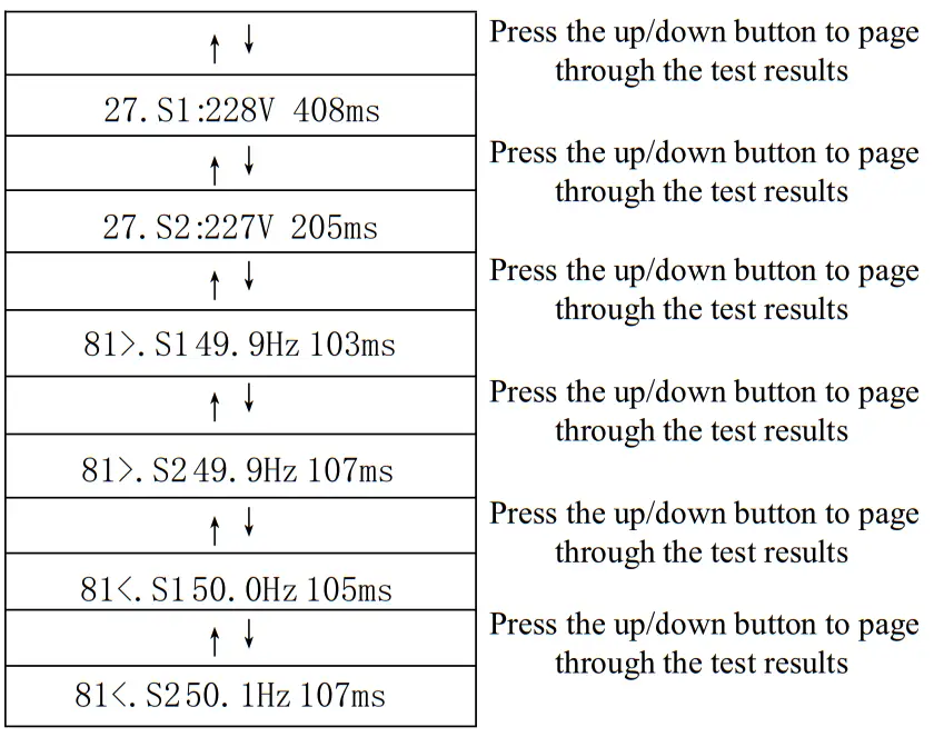
| Object | Description |
| 27.S1 | Under voltage protection |
| 27.S2 | Under voltage protection |
| 59.S1 | Over voltage protection |
| 59.S2 | Over voltage protection |
| 81<S1 | Under frequency protection |
| 81<S2 | Under frequency protection |
| 81>S1 | Over frequency protection |
| 81>S2 | Over frequency protection |
Fault diagnosis and solutions
The inverter is easy to maintain. When you encounter the following problems, please refer to the Solutions below, and contact the local distributor if the problem remains unsolved. The following table lists some of the basic problems that may occur during the actual operation as well as their corresponding basic solutions.
Fault diagnosis table
| Content | Codes | Solutions |
| DischgOverCur |
00 |
Battery discharge over current. (1) Nothing need to do, Wait one minute for the inverter to restart. (2) Check whether the load is in compliance with the specification.| (3) Cut off all the power and shut down all the machines; disconnect the load and plug in to restart machines, then check |
| Over Load | 01 | The load power is greater than other power(PV,BAT). (1) Check whether the load is in compliance with the maximum power of the machine. (2) Cut off all the power and shut down all the machines; disconnect the load and plug in to restart machines, then check whether the load is short circuited if the fault has been eliminated.(3) Contact customer service if error warning continues. |
| Bat Disconnect | 02 | Battery Disconnect. (Battery voltage not identified) (1) Check whether the battery is connected. (2) Check if battery wiring port is open circuited. (3) Contact customer service if error warning continues. |
| Bat Under Vol | 03 | Battery voltage low that normal range. (1) Checking System Settings, If so, power off and restart. (2) Check if the grid power down. If so, waiting for the grid power up, the inverter will automatically charge. (3) Contact customer service if error warning continues. |
| Bat Low capacity | 04 | Battery Low that setting capacity.(SOC<100%-DOD) |
| Bat Over Vol | 05 | The battery voltage is greater than the Inverter maximum voltage. (1) Checking System Settings, If so, power off and restart. (2) Contact customer service if error warning continues. |
| Gird low vole | 06 | Grid voltage is abnormal (1) Check if the grid is abnormal. (2) Restart the inverter and wait until it functions normally. (3) Contact customer service if error warning continues. |
| Grid over vole | 07 |
| Grid low frees | 08 | Grid Frequency is abnormal. (1) Check if the grid is abnormal. (2) Restart the inverter and wait until it functions normally. (3) Contact customer service if error warning continues. |
| Grid overfired | 09 | |
|
foci over |
10 |
Inverter GFCI exceeds standard. (1) Check PV string for direct or indirect grounding phenomenon. (2) Check peripherals of machine for current leakage. (3) Contact the local inverter customer service if fault remains unremoved. |
|
bus under vol |
13 |
BUS voltage is lower than normal. (1) Check the input mode setting is correct. (2) Restart the inverter and wait until it functions normally. (3) Contact customer service if error warning continues. |
|
bus over vole |
14 |
BUS voltage is over maximum value.. (1) Check the input mode setting is correct. (2) Restart the inverter and wait until it functions normally. |
| IN over cur | 15 | The inverter current exceeds the normal value. (1) Restart the inverter and wait until it functions normally. |
| Chg over cur | 16 | Battery charge current over than the Inverter maximum voltage. (1) Restart the inverter and wait until it functions normally. |
|
Bus vole orc |
17 |
Bus voltage instability. (1) Check the input and output mode setting is correct. (2) Restart the inverter and wait until it functions normally. |
| IN under vole | 18 | INV voltage is abnormal (1) Check if the INV voltage is abnormal. (2) Restart the inverter and wait until it functions normally. (3) Contact customer service if error warning continues. |
| IN over vole | 19 | |
|
InvFreqAbnor |
20 |
INV frequency is abnormal (1) Check if the INV frequency is abnormal. (2) Restart the inverter and wait until it functions normally. (3) Contact customer service if error warning continues. |
| gift temp high | 21 | The inverter temperature is higher than the allowed value (1) Cut off all the power of the machine and wait one hour, then turn on the power of the machine. |
| bat over temp | 23 | Battery temperature is higher than the allowed value. (1) Disconnect the battery and reconnect it after an hour. |
| bat Under Temp | 24 | Battery temperature is low than the allowed value. (1) Check the ambient temperature near the battery to see if it meets the specifications. |
| BMS comm. fail | 27 | Communication between lithium battery and inverter is abnormal. (1) Check the cable, crystal, Line sequence. (2) Checking the Battery switch. |
| Fan fail | 28 | Fan fail (1) Check whether the Inverter temperature is abnormal. (2) Check whether the fans run properly.(If you can see it) |
| Grid Phase err | 30 | The grid fault phase. (1) Check power grid wiring |
| Arc Fault | 31 | PV Arc Fault (1) Check Photovoltaic panels, PV wire. (2) Contact customer service if error warning continues. |
| bus soft fail | 32 | (1) Restart the inverter and wait until it functions normally. (2) Contact customer service if error warning continues. |
| ink soft fail | 33 | |
| bus short | 34 | |
| ink short | 35 | |
| fan fault | 36 | Fan fault. (1) Check whether the Inverter temperature is abnormal. (2) Check whether the fans run properly.(If you can see it) |
| PV is low | 37 | (1) Check if the PE line is connected to the inverter and is connected to the ground. (2)Contact customer service if error warning continues. |
| Bus Relay Fault | 38 | (1) Restart the inverter and wait until it functions normally. (2) Contact customer service if error warning continues. |
| Grid Relay Fault | 39 | |
| EPS rly fault | 40 | |
| Gucci fault | 41 | |
| Softest fail | 44 | |
| System fault | 45 | |
| Current Dover | 46 | |
| Voltage Dover | 47 |
Note: If an error occurs that is not listed in the table, Please Contact customer service.
INVT Solar Technology (Shenzhen) Co., Ltd.
Address: 6th Floor, Block A, INYT Gunging Technology Building,
Songhai Road, Darion, Gunging District, Shenzhen, China.
Postcode: 518106
Web: wev.inrt-solar.com
E-mail: solarlinvt.com.cn