Contents
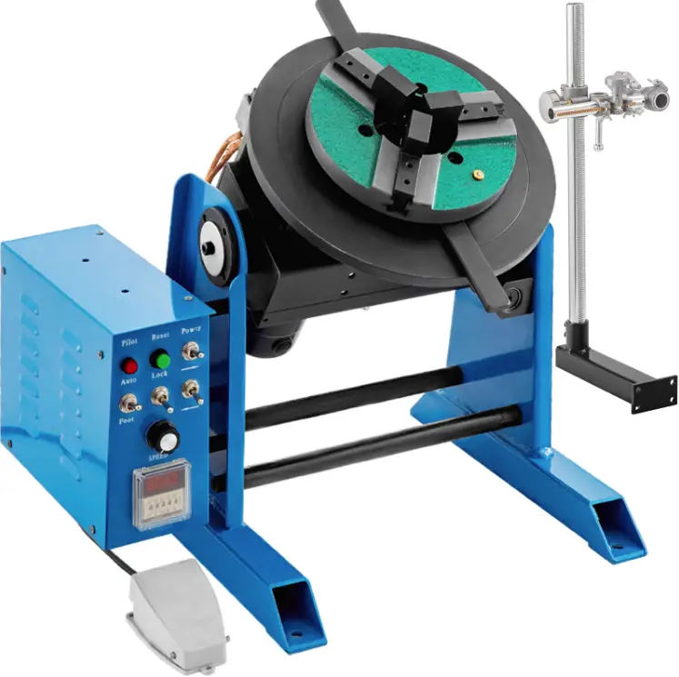
 VEVOR HD-30 Rotary Welding Positioner
Introduction
WARNING A procedure, which, if not properly followed, may cause injury to the operator or others in the operating area.
Equipment Identification
The identification number specification or model, and serial number of this unit usually appear on a nameplate attached to the control panel, record these numbers for future reference.
Receipt of Equipment
When you receive the equipment, check it against the shipping documents. Make sure it is complete and inspect the equipment for possible damage during shipping. If there is any damage, notify the carrier immediately to file a claim. Furnish complete information concerning damage claims or mistake(s) in shipment to our company. Include the equipment identification number along with a description of the parts in question. Move the equipment to the installation site before uncrating the unit. Use care to avoid damaging the equipment when using bars, hammers, etc. to uncrate the unit.
Specification
| No | MODEL | Power input | Horizontal loading capacity | Vertical loading capacity | Working table diameter | Working table height | Working table tilting angle | Working table rotation speed | Rotation motor | Overall length(A) | Overall width(B) | Overall height(C) | Cable terminal | Table Centre Through Hole Dia | Net weight | Applicable chuck |
|---|---|---|---|---|---|---|---|---|---|---|---|---|---|---|---|---|
| 1 | HD-30 | AC110V 50Hz | 30 Kg | 15 Kg | 310 mm | 380 mm | 0-90 | 1-15 r/min | 80 W | 380 mm | 380 mm | 380 mm | 30-50mm2 m2 | 25 mm | 35 Kg | KD/80-3/4 |
| HD-50 | AC220V 50Hz | 50 Kg | 25 Kg | 310 mm | 380 mm | 0-90 | 0.5-7 r/min | 120 W | 380 mm | 380 mm | 380 mm | / 30-50mm2 m2 | 45/75/14 mm | 35 Kg | KD/80-3/4 | |
| HD-100 | AC220V 50Hz | 100 Kg | 50 Kg | 400 mm | 520 mm | 0-90 | 0.5-7 r/min | 120 W | 490 mm | 530 mm | 520 mm | / 30-50mm2 m2 | 45/75/1.25 mm | 70 Kg | KD-200/3 | |
| HD-200 | AC220V 50Hz | 100 Kg | 50 Kg | 400 mm | 520 mm | 0-90 | 0.5-7 r/min | 120 W | 490 mm | 530 mm | 520 mm | / 30-50mm2 m2 | 45/75/1.25 mm | 78 Kg | KD-200/3 | |
| HD-300 | AC220V 50Hz | 300 Kg | 150 Kg | 500 mm | 650 mm | 0-90 | 0.2-2.5 r/min | 200 W | 680 mm | 660 mm | 650 mm | / 30-50mm2 m2 | 90 mm | 102 Kg | KD-300/4 |
Usage Instructions
- When you receive the equipment, check it against the shipping documents. Make sure it is complete and inspect the equipment for possible damage during shipping. If there is any damage, notify the carrier immediately to file a claim.
- Move the equipment to the installation site before uncrating the unit. Use care to avoid damaging the equipment when using bars, hammers, etc. to uncrate the unit.
- Record the identification number specification or model and serial number of this unit for future reference.
- Connect the power input according to the specifications listed in the table above.
- Place the object to be welded on the working table and adjust the working table height as per your requirement.
- Adjust the working table tilting angle and rotation speed as per your requirement.
- Turn on the power using the power on/off switch (K1) on the control panel.
- Use the forward/reverse switch (K2) to adjust the motion of the object to be welded.
- Adjust the speed using the speed adjustment switch (K4) on the control panel.
- If you face any issues with the equipment, refer to the troubleshooting guide provided in the manual.
- Pour lubricating oil per week in the lube hole provided.
- While choosing the working table angle, hold the locking screw tightly in the drop lock mechanism.
WARNING A procedure, which, if not properly followed, may cause injury to the operator or others in the operating area.
Equipment Identification
The identification number specification or model, and serial number of this unit usually appears on a nameplate attached to the control panel, record these numbers for future reference.
Receipt of Equipment
When you receive the equipment, check it against the shipping documents, Make sure it is complete and inspect the equipment for possible damage during shipping, if there is any damage, notify the carrier immediately to file a claim. Furnish complete information concerning damage claims or mistake(s) in shipment to our company Include the equipment identification number along with a description of the parts in question. Move the equipment to the installation site before uncrating the unit. Use care to avoid damaging the equipment when using bars, hammers, etc. to uncrate the unit.
SPECIFICATION
|
No
. |
MODEL |
UNIT |
HD-30 |
HD-50 |
HD-100 |
HD-200 |
HD-300 |
|
1 |
Power input |
/ |
AC110V 50Hz | AC220V 50Hz | AC220V 50Hz | AC220V 50Hz | AC220V 50Hz |
|
2 |
Horizontal loading capacity |
Kg |
30 |
50 |
100 |
100 |
300 |
|
3 |
Vertical loading capacity |
Kg |
15 |
25 |
50 |
50 |
150 |
|
4 |
Working table diameter |
mm |
310 |
310 |
400 |
400 |
500 |
|
5 |
Working table height |
mm |
380 |
380 |
520 |
520 |
650 |
|
6 |
Working table tilting angle |
° |
0-90 |
0-90 |
0-90 |
0-90 |
0-90 |
|
7 |
Working table rotation speed | r/mi n |
1-15 |
0.5-7 |
0.5-7 |
0.5-7 |
0.2-2.5 |
|
8 |
Rotation motor |
W |
80 |
120 |
120 |
120 |
200 |
|
9 |
Overall length(A) |
mm |
380 |
380 |
490 |
490 |
680 |
|
10 |
Overall width(B) |
mm |
380 |
380 |
530 |
530 |
660 |
|
11 |
Overall height(C) |
mm |
380 |
380 |
520 |
520 |
650 |
|
12 |
Cable terminal |
/ |
30-50m
m2 |
30-50m
m2 |
30-50mm2 |
30-50mm2 |
30-50mm2 |
|
13 |
Table Centre Through Hole Dia |
mm |
25 |
25 |
45/75/14
0 |
45/75/1
40 |
90 |
|
14 |
Net weight |
Kg |
35 |
35 |
70 |
78 |
102 |
|
15 |
Applicable chuck |
/ |
KD/80- 200 | KD/80- 200 | KD-200/3 00 | KD-200/ 300 | KD-300/4 00 |
DEMENSIONS
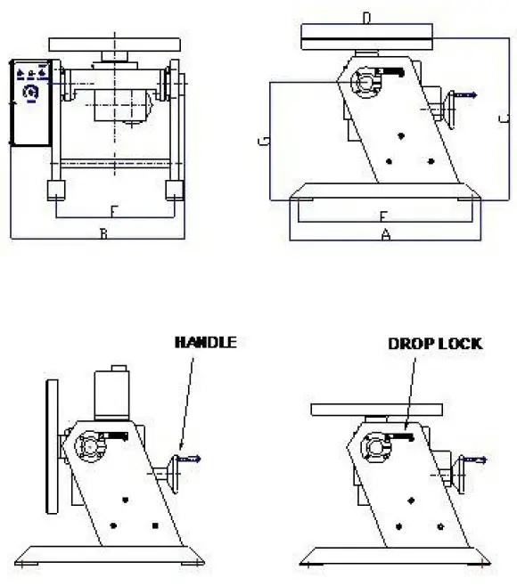
NOTE
- HD-50: E=340mm F=320 mm
- HD-100: E=480mm F=400mm
- HD-200: E=480mm F=400mm
- HD-300: E=590mm F=475mm
- LUBE HOLE: Pour lubricating oil per week.
- DROP LOCK: Holding the locking screw tightly when choosing the working table angle.
CONTROL PANEL

TROUBLESHOOTING GUIDE
| NO. | SYMPTOM | POSSIBLE CAUSE | REMEDY |
|
1 |
The power pilot does not lit |
1. Power fuse is burnt.
2. LED burnt. 3. Power switch is burnt. 4. No power input. |
1. Replace a new fuse.
2. Replace the LED. 3. Replace the switch. 4. Check the switch or replace it. |
|
2 |
Speed Adjustment no Motion. |
1. Damaged potentiometer.
2. Motor control PCB no output. |
1. Check if the potentiometer
is 10ΚΩ, otherwise replace it. 2. Replace a new motor control PCB. |
|
3 |
Footswitch no motion |
The foot switch is damaged. |
Check the foot switch or replace it. |
|
4 |
Forward/Reverse no output |
The Forward/Reverse switch is damaged. |
Check the switch or replace it. |
| 1. Motor has power input but no motion.
2. Motor control PCB has no power input 3. Motor control PCB is damaged. |
1. Replace a new motor. | ||
| 5 | |||
| Motor no motion | 2. Check the transformer or replace it. | ||
| 3. Replace the control PCB. |
ILLUSTRATION OF THE CONTROL PCB ADJUSTMENT
- Attention when choosing the switches of input and output voltage(115V/230V), disconnect the power timely when doing the switch.
- ACCEL is time accelerating adjustable potentiometer When the output voltage is 0-90VDC, from 0.5 seconds to 11 seconds can be adjustable; When the output voltage is 0-180VDC, from 0.5 seconds to 22 seconds can be adjustable.
- DECEL is decelerating adjustable potentiometer. When the output voltage is 0-90 VDC, the longest time is 13 seconds; When the output voltage is 0-180 VDC, the longest time is 25 seconds.
- MAX SPD is a maximal speed adjustable potentiometer; Twist it to the end clockwise to set the maximum speed.
- MIN SPD is a minimum speed adjustable potentiometer; Twist it to the end clockwise to set the zero speed anticlockwise.
- INHIBIT is an external enable control side, When this function works, the speed of the motor is set by MIN SPD.
- TORQUE、IRCOMP is torque and laden adjustable potentiometers.
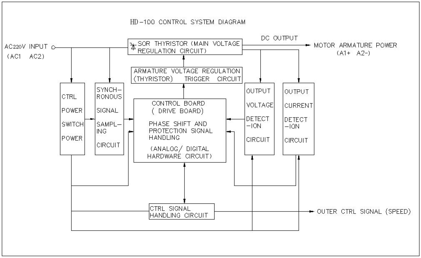
CONTROL SCHEMATIC DIGRAM