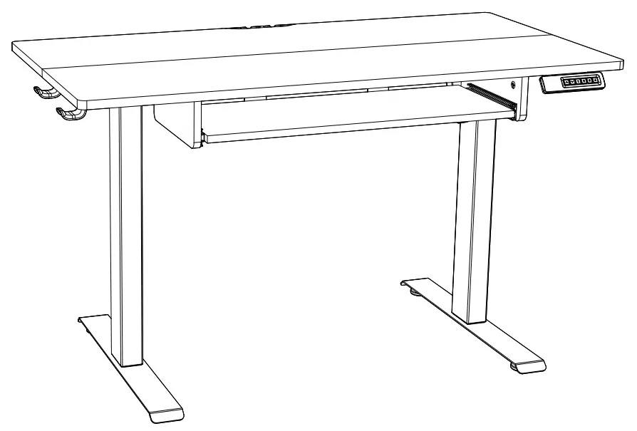
MARSAIL TZESD14B Electric Standing Desk Instruction
Contents
Specifications
| Height Adjustment Range: | 27.5″-46.7″ (70-118cm) | |
| Power Input | 100V-240V |  |
| Max Speed | 25mm/s |  |
| Operating Noise | <50dB |  |
| Max Load | 176 lbs / 80kg |  |
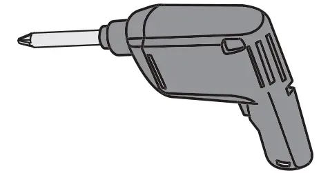
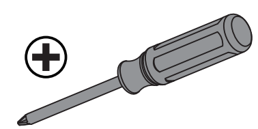
Tools Needed (not included)
- Drill
OR - Phillips Screwdriver
Supplied Parts and Hardware
Step 1
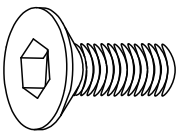
| Bolt | M6 x 25mm | (A) x 12 |
 |
| Bolt | M6 x 16mm | (B) x 4 |
 |
| Set Screw | (C) x 2 |
 |
|
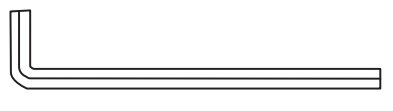
| Allen Wrench | 5/32″ (4mm) | (D) x 1 |
 |
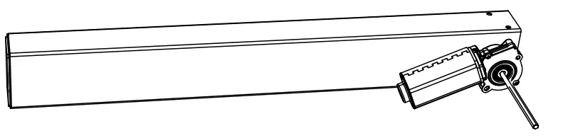
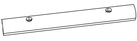
| Crossbar | (01) x 1 |
 |
|
| Left Desk Leg | (02) x 1 |
 |
|
| Right Desk Leg | (03) x 1 |
 |
|
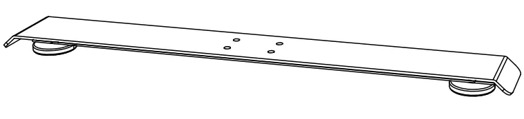
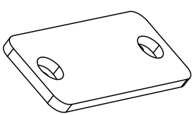
| Leg Base | (04) x 2 |
 |
|
| Side Plate | (05) x 2 |
 |
|
| Transmission Rod | (06) x 1 |
 |
|
| Rod Coupler | (07) x1 |
 |
|
| Wrench | (08) x 1 |
 |
|
Step 2
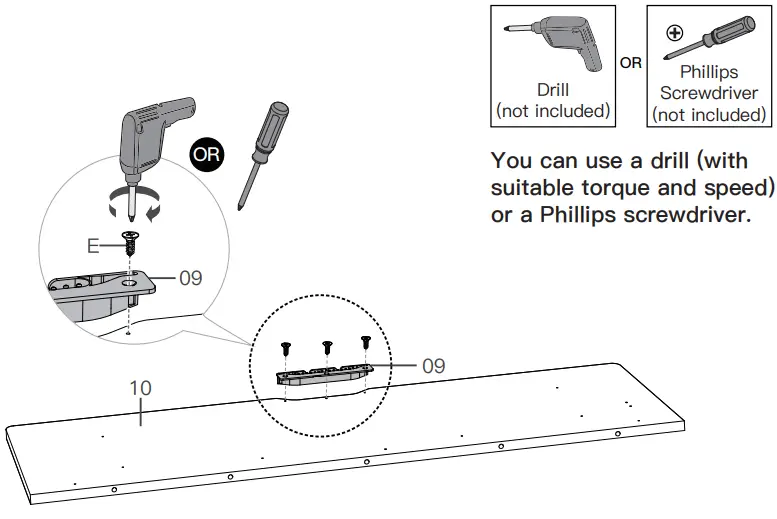
| Screw | ST3.9 x 13mm | (E) x 3 |
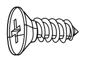 |
| Screw | ST5 x 16mm | (F) x 6 |
 |
| Desktop Panel Connector | (H) x 3 |
 |
|
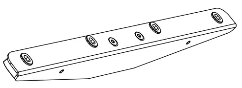
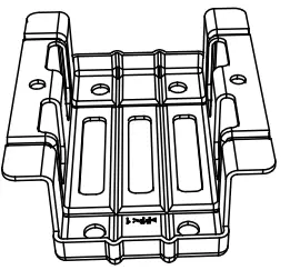
| Cable Management Bracket | (09) x 1 |
 |
|
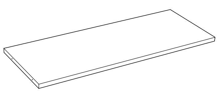
| Desktop | (10) x 1 |
 |
|
| Wood Dowel Pin | (G) x 5 (for 48″) x 6 (for 55″ |
 |
|
| Note: An extra wood dowel pin is provided for the longer 55″ desk. | |||
Step 3
| Screw | ST5 x 16mm | (F) x 18 |
 |
| AC Adapter Holder | (11) x 1 |
 |
|
| Storage Hook | (12) x 2 |
 |
|
| Controller | (13) x 1 |
 |
|
| AC Adapter | (14) x 1 |
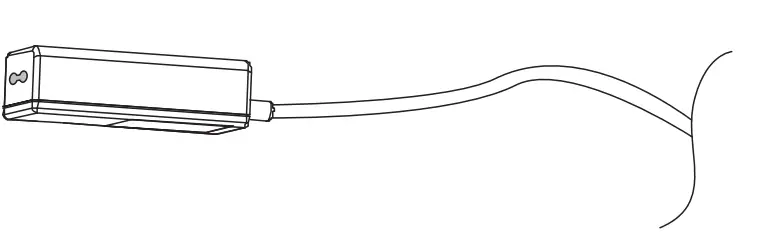 |
|
Step 4
| Screw | ST3.9 x 13mm | (E) x 14 |
 |
| Cam Bolt | (I) x 4 |
 |
|
| Cam Lock | (J) x 4 | 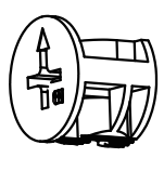 |
|
| Wood Dowel Pin | (G) x 2 |
 |
|
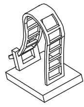
| Keyboard Tray | (15) x 1 |
 |
|
| Drawer Slide | (16) x 2 |
 |
|
| Left Keyboard Tray Side Plate | (17) x 1 |
 |
|
| Right Keyboard Tray Side Plate | (18) x 1 |
 |
|
| Keyboard Stopper | (19) x 2 |
 |
|
Step 5
| Power Cable | (20) x 1 |
 |
| Cable Clip | (21) x 4 |
 |
Assembling the Frame
Step 1:
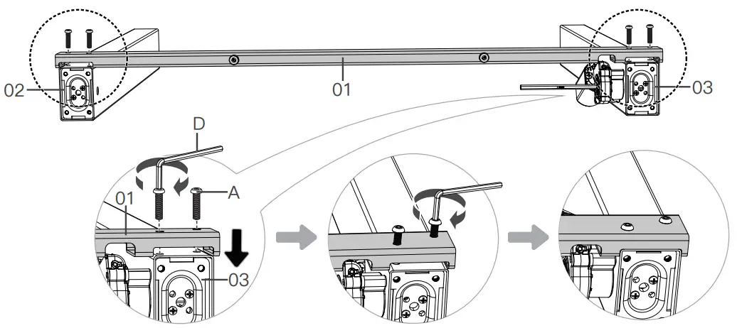
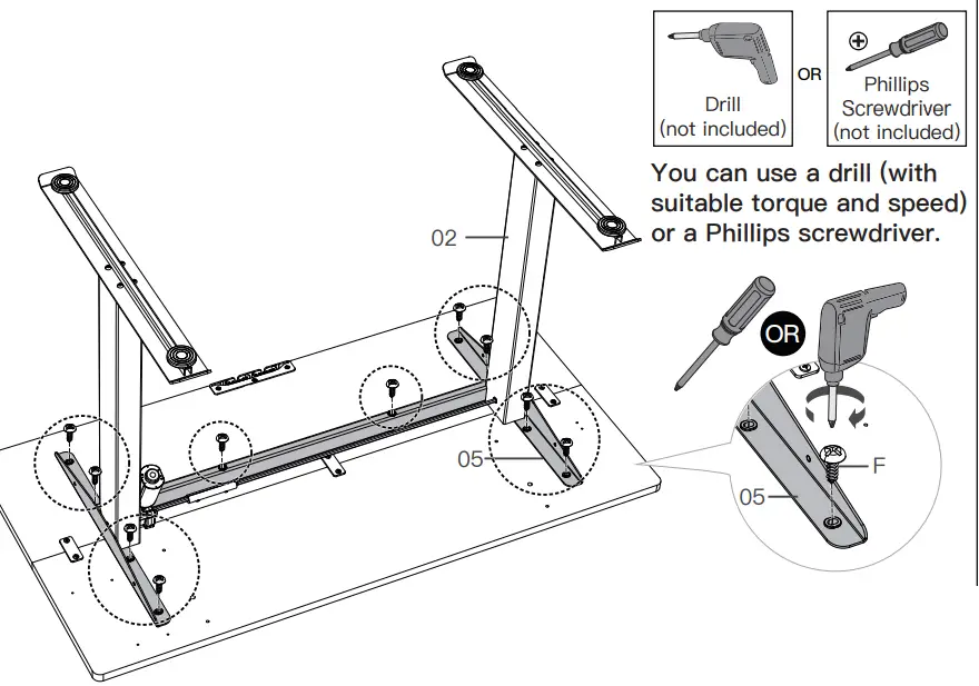
Align holes in the crossbar with holes in the desk legs, and insert four bolts. Partially and then fully tighten each pair of bolts, making sure the legs fit smoothly into the crossbar grooves.
Insert four bolts through each leg base and into each leg. Partially and then fully tighten the bolts in each leg.
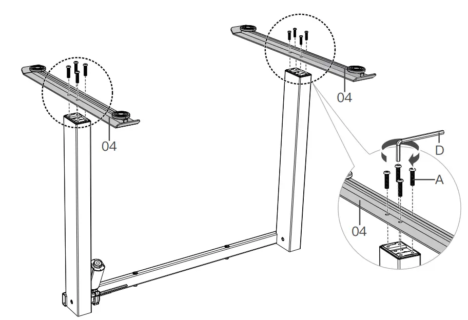
Attach the side plates.

Slide the rod coupler onto the end of the motor drive shaft on the right leg.
Adjust uneven desk legs
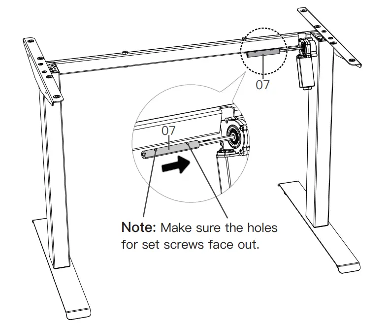
Before attaching the transmission rod, measure the heights of the two desk legs to see if they are set at the same level. If not, insert the transmission rod into the hole in the left leg. Turn the rod with the wrench to adjust the left leg so it’s level with the right leg. Turn the rod clockwise to raise the left leg or anti-clockwise to lower it.

Ensure the transmission rod is properly inserted into the hole in the left leg. Slide the rod coupler to the left to connect with the other end of the transmission rod.
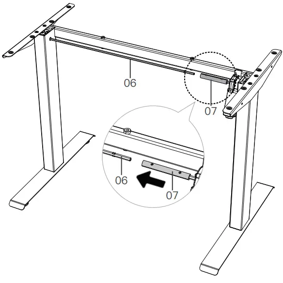
Note: If the transmission rod doesn’t fit smoothly into the rod coupler, fine-tune with the wrench.

Use the set screws to secure the rod coupler.

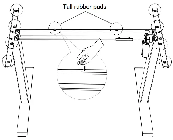
Ensure the rubber pads are attached to the frame. If any have fallen off, reattach them or use the spare rubber pads.
Assembling the Desktop
Step 2:
Attach the cable management bracket to the desktop.
For the 48″ long desk, use the five wood dowel pins to join the two desktop panels together.

For the 55″ long desk, use the six wood dowel pins to join the two desktop panels together.
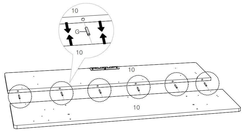
Secure the desktop panels with the connectors.
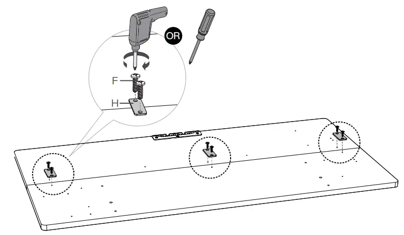
Attaching the Desktop
Step 3:
Attach the frame to the desktop.
Note: An off-center screw hole is not a problem. The pre-drilled holes are only guides for easier screw-in. If you have any questions or issues, please contact us at [email protected].
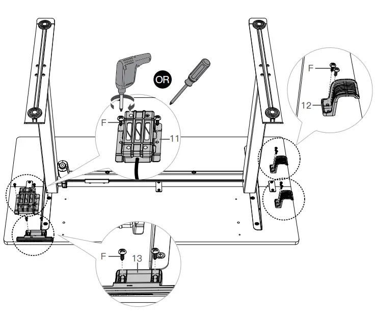
Put the AC adapter into the holder

Attach the controller, AC adapter with holder, and storage hooks to the desktop
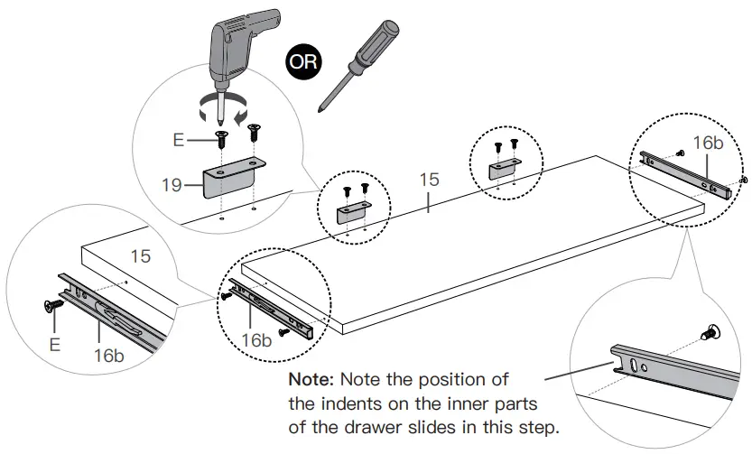
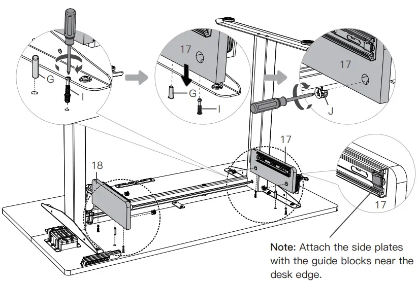
Assembling the Keyboard Tray
Step 4:
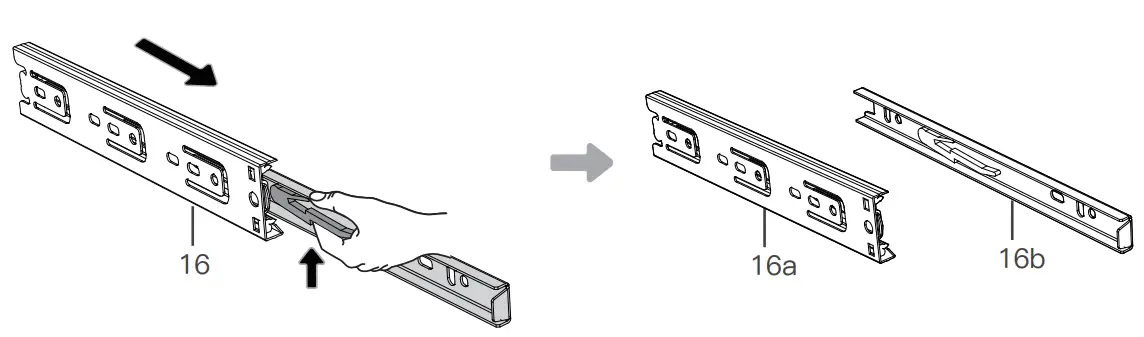
Detach the inner and outer parts of the two drawer slides.
Attach the outer parts of the two drawer slides to the left and right keyboard tray side plates.

Attach the keyboard stoppers. Then attach the inner parts of the two drawer slides to the keyboard tray.
Screw the cam bolts and push the wood dowel pins into the desktop. Attach the keyboard tray side plates to the desktop. Secure with cam locks.
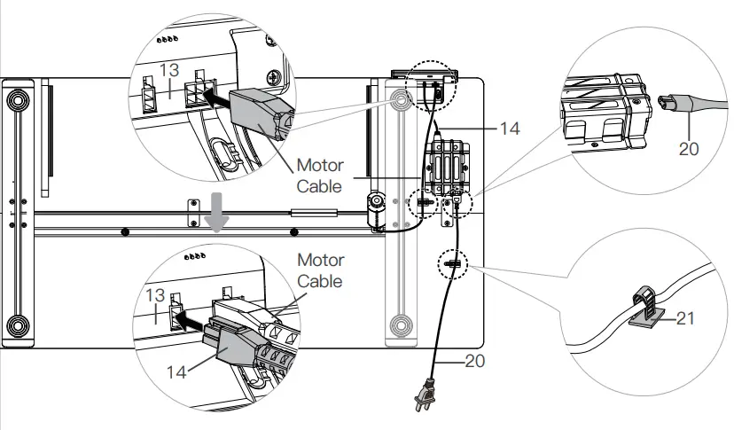
Connecting the Cables
Step 5:
Inserting the Keyboard Tray
Step 6:

Using the Controller
Note: Ensure that there are no obstacles when using the desk, that the desktop is not right next to the wall, and that all cables are long enough for the desk to move up and down freely. When the controller screen is off (power-saving mode), press any button to wake it before operating the desk.
Suggestion: Set the most comfortable height when you sit down to  and the most comfortable height when you stand up to
  . The other two presets can be set for another user or to other heights you want to use.
| Raise the Desk Press the  button to raise the desk continuously until it reaches the highest position of 46.7″ (118cm) or the button is released. button to raise the desk continuously until it reaches the highest position of 46.7″ (118cm) or the button is released. |
| Lower the Desk Press the  button to lower the desk continuously until it reaches the lowest position of 27.5″ (70cm) or the button is released. button to lower the desk continuously until it reaches the lowest position of 27.5″ (70cm) or the button is released. |
| Save Height Settings Four heights can be stored. Press and hold the / /  / / |
| Select Height Setting 1 Press the button, and the desk will move to the height that was previously set for that button. Press any button to stop the desk. |
| Select Height Setting 2 Press the button, and the desk will move to the height that was previously set for that button. Press any button to stop the desk. |
| Select Height Setting 3 Press the button, and the desk will move to the height that was previously set for that button. Press any button to stop the desk. |
| Select Height Setting 4 Press the |
Settings |
|
| Reset |
|
| Lock / Unlock | Press and hold and buttons together for 3 seconds to turn the lock on. The screen will display ‘LOC’ and the buttons will be disabled. Repeat to turn the lock off. |
| Change Display Height Units | Press and hold and buttons together for 3 seconds to switch the display height unit. The default unit is inches. |
| Change Collision Detection Sensitivity |
|
| Set / Clear Lowest Limit |
|
| Set / Clear Highest Limit |
|
| Troubleshooting | |
|
|
Thank
Thank you for choosing this product! We strive to provide you with the best
quality products and service in the industry. Should you have any issues,
please don’t hesitate to contact us at [email protected]