IDEC EU2B Flameproof and Increased Safety Control Units Instruction Manual
Contents
Safety Precautions
In this operation instruction manual, safety precautions are categorized in order of importance to Warning and Caution:
 WARNING:
Warning notices are used to emphasize that improper operation may cause severe personal injury or death.
CAUTION:
Caution notices are used where inattention might cause personal injury or damage to equipment.
WARNING:
(General requirements)
- Use the EU2B control units that are applicable for use in hazardous areas, otherwise explosion or fire hazard may result. (Hazardous area: potentially explosive atmosphere where explosive gas or vapor may exist) Because the EU2B control unit is a Ex component, it cannot be be used as an explosion-proof equipment on its own. To use the EU2B control units in Japan, it should be certifified by TIIS (Technology Institution of Industrial Safety) as a finished product.
- EU2B control units can be installed only in zones 1 and 2. Do not use in zone 0.
- Turn power off to the EU2B control units before installation, removal, wiring, maintenance, or inspection, otherwise explosion, fire hazard, or electric shock may result.
- Special expertise is required to install, wire, operate, maintain, and inspect the EU2B control units. People without such expertise must not use the EU2B control units, otherwise damage or accident may result
- Do not disassemble, repair, or modify the EU2B control units, otherwise damage or accident may result.
- Do not use a damaged the EU2B control units, otherwise damage or accident may result.
(Wiring and operation)
- When connecting with external devices, make sure that each cable is connected to the correct terminal, otherwise electric shock, fire hazard, or explosion may result.
- Use wires of a proper size to meet voltage and current requirements. Tighten the M3.5 terminal screws to a tightening torque of 1.0 to 1.3 Nm. Incorrect wiring may cause abnormal temperature rise and lead to fire hazard and explosion.
- Operate the EU2B control units under the rated current and voltage specified in this instruction manual, otherwise short-circuiting, fire hazard, or explosion may result.
(Maintenance and inspection)
- When measuring the insulation resistance of the control units, make sure that potentially explosive atmosphere of explosive gas or vapor does not exist in the vicinity, otherwise explosion or fire hazard may result. Do not touch the terminal carelessly. Otherwise, electric shock may result.
CAUTION:
(General requirements)
- The EU2B control units are exclusively designed for the EC2B flameproof and increased safety control box. When using the EU2B control units for other purposes, make sure that the operating conditions are appropriate.
- When using the emergency stop switch for safety-related equipment in a control system, to make sure of correct operation, refer to the safety standards and regulations in each country and region depending on the application purpose of the actual machines and installations. Before using the emergency stop switch, perform risk assessment to make sure of safety.
(Opening the shipping carton)
- Check that the product is what you have ordered. Using an incorrect model might result in malfunction or accident.
(Installation)
- Read this instruction manual to make sure of correct installation of the EU2B control units. Install the EU2B control units without getting in the substances such as dust, concrete powder, or metal powder, otherwise contact failure or insulation failure may result.
(Operation)
- Stop operation immediately if abnormal operation occurs. Otherwise, a secondary accident may occur.
(Maintenance and inspection)
- The surface temperature of the EU2B control units may become extremely high during operation. Before maintenance or inspection of the EU2B control units, be sure to wear gloves to prevent burn on your hand.
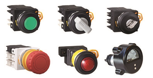
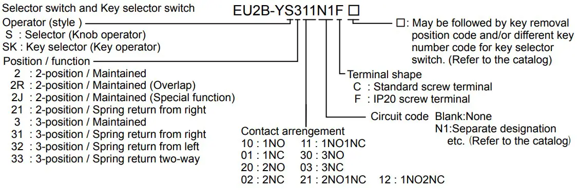
Type Numbers


Product Specifications
- General Specifications
Applicable Standards IEC/EN 60079-0, IEC/EN 60079-1, IEC/EN 60079-7IEC/EN 61241-0, IEC/EN 61241-1, IEC/EN 60079-31IEC/EN 60947-1, IEC/EN 60947-5-1IEC/EN 60947-5-5 (Emergency stop switch)IEC/EN 60051-1, IEC/EN 60051-2, IEC/EN 60051-9(Meter) Explosion protection Group and category II2GD Type of Explosion protection Ex de IIC, Ex tD A21 IP65Ex de IIC Gb, Ex tb IIIC Db IP65(Meter) Test certificated PTB 08 ATEX 1053 U / PTB 08 ATEX 1003 U / PTB**ATEX****U Degree of protection (IEC/EN 60529) From panel front IP65 Terminal IP20 (EU2B-Y***F), None (EU2B-Y***C) Standard operating environment Ambient temperature -20 to +50℃ (no freezing) Relative humidity 45 to 85%RH (no condensation) Altitude 2,000m maximum Pollution degree 3 Shock resistance Operating extremes 100 m/s2, Emergency stop switch: 150 m/s2 (Without Meter) Damage limits 1,000 m/s2 Vibration resistance Operating extremes 5 to 55 Hz, amplitude 0.5 mm Emergency stop switch:5 to 500 Hz, amplitude 0.35 mm, acceleration 50 m/s2(Without Meter) Damage limits 30 Hz, amplitude 1.5 mm Emergency stop switch:5 to 500 Hz, amplitude 0.35 mm, acceleration 50 m/s2 - Pushbutton swtich, Selecter switch, Key selecter switch and Emergency stop switch (Type EU2B-YB/ EU2B-YS/ EU2B-YSK/ EU2B-YBV)
Contact RatingRated Insulation Voltage (Ui) 600V Thermal Current (Ith) 10A Rated Operating Voltage(Ue) 24V 120V 240V 500V Rated Operating Current(Ie) AC50/60Hz Resistive load (AC12) 10A(*) 10A(*) 6A 2.8A Inductive load (AC15) 10A(*) 6A 3A 1.4A DC Resistive load (DC12) 8A 2.2A 1.1A – Inductive load (DC13) 4A 1.1A 0.55A – *)10A (< 2 contact blocks by one control unit), 9A (= 3 contact blocks by one control unit)
Minimum switching capacity : 5 mA at 3V AC/DC (applicable range may vary with operating conditions and load types)
SpecificationsContact resistance 50 mV maximum (initial value) Impulse Withstand Voltage (Uimp) 6kV Insulation Resistance 100 MV minimum (500V DC megger) Mechanical Life Pushbutton swtich :1,000,000 operations minimum Selecter switch : 500,000 operations minimum Key selecter switch : 500,000 operations minimum Emergency stop switch : 50,000 operations minimum Electrical Life Pushbutton swtich : 250,000 operations minimum (Operating Frequency : 1,800 operations/hour)
Selecter switch : 250,000 operations minimum (Operating Frequency : 900 operations/hour)
Key selecter switch : 250,000 operations minimum (Operating Frequency : 900 operations/hour)
Emergency stop switch : 50,000 operations minimum (Operating Frequency : 900 operations/hour)
Contact block 3 contacts maximum. Short-circuit Protective Device 250V/10A fuse (Type aM IEC60269-1/IEC6026-9-2) Conditional Short-circuit Current 1000A Minimum Direct Opening Force Emergency stop switch: 60 N Minimum Direct Opening Travel Emergency stop switch: 7.0 mm Maximum Travel Emergency stop switch: 9.0 mm Weight (approx.) EU2B-YB111C : 92g, EU2B-YS211C : 98g EU2B-YSK211C : 120g, EU2B-YBV302C : 120g Notes for Operation
Contact bouncing When the control unit is operating, the contacts will bounce. When designing a control circuit, take the contact bounce time into consideration (reference value: 20 ms). - Pilot Light (Type EU2B-YL)
Rated insulation voltage (Ui) 500 V Rated Operating Voltage (Ue) AC/DC 6, 12, 24V (Full voltage type) AC 100/110, 115, 120, 200/220, 230, 240, 380, 400/440, 480V (Transformer type) Impulse Withstand Voltage (Uimp) 4kV Insulation Resistance 100 M minimum (500V DC megger) Light source LED lamp (Type LSTD by IDEC) Colors Amber, Blue, Green, Pure White, Red, White, Yellow Frequency (AC) 50/60 Hz Rated Power Consumption (approx.) 0.3W (Full voltage type), 1.5VA (Transformer type) life (reference value) Applox 40,000 hours Weight (approx.) 108g (Full voltage type), 150g (Transformer type) Notes for Operation
The LED built-in lamp is super bright type. Note that the LED lamp may turn on even when the power is turned off because of induction.
IDEC does not guarantee exchange of an LED lamp, because it will affect explosion protection characteristics. Call IDEC when you need to replace LED lamps. - Meter(EU2B-YM)
Accuracy Class 2.5 Insulation Resistance 100MΩ minimum(500V DC megger) AC ammeter Rated Insulation Voltage(Ui) 300V Principle of action Moving-iron instrument Impulse Withstand Voltage(Uimp) 4kV Power Consumption 1VA Specification of Measuring Range 5A, 10A, 30A, 50A etc Specification of Input Current 1A, 5A Specification of Overload Scale 3 times etc DC ammeter DC voltmeter Rated Insulation Voltage(Ui) 150V Principle of action Permanent-magnet moving -coil instrumen Impulse Withstand Voltage(Uimp) 2.5kV Specification of Input: DC ammeter
DC voltmeter0 to 1mA DC, 4 to 20mA DC etc.
0 to 10V DC etcPower Consumption 0.15W max. Weight(approx.) 270g Notes for Operation
- For AC ammeter of measuring range of 10A or avobe, use a current transformer commercially available. Install the current transformer in the non-hazardous area.
- Terminal polarity of meter.
Note that the upper terminal is positive (No.1) and the lower terminal is negative (No.2) when installed on the control box. - Zero-setting the pointer and setting the set pointer Using a flat screwdriver with the tip of 0.8t×5w or smaller, adjust the pointer and the set pointer by turning the shafts as shown at the right. Do not apply excessive force on the shaft, otherwise the shaft will be damaged.
- DC voltmeter and DC ammeter do not require zero adjustment.

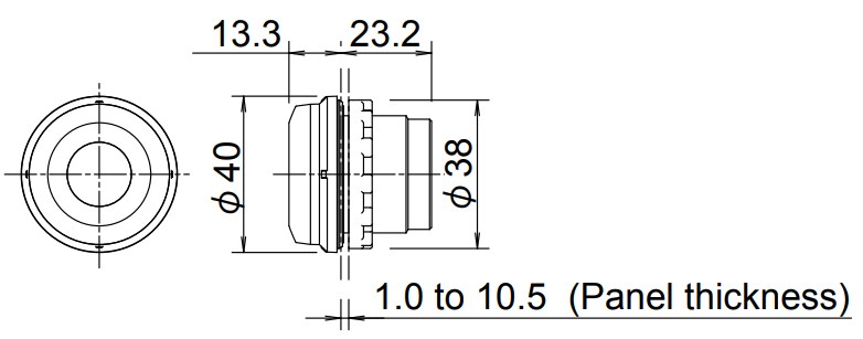
Arrangement and Mounting
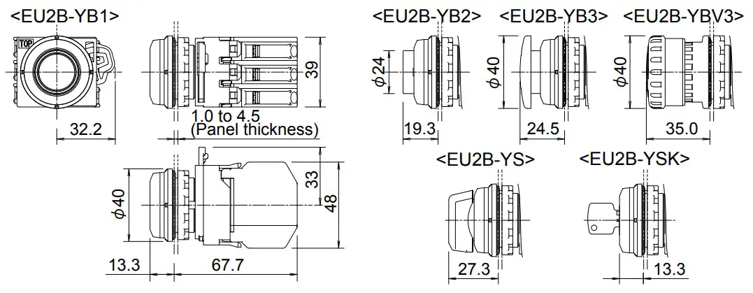
- Dimension
- Parts Description
- Panel thickness/ Mounting hole layout
- Panel thickness: 1.0 to 4.5 mm
Mounting hole layout: See the right figures. (*)The meter can be mounted on the top mounting holes of the standard 50mm mounting centers. The meter can be mounted on any mounting hole with the 70mm or larger mounting center. - Panel mounting
To remove the contact unit (for pilot lights, remove the lamp unit) from the operator (or lens unit). To remove the locking ring from the operator. To insert the operator into the panel cut-out from the front, tighten the locking ring from the back, then install the contact unit to the operator.

To remove the contact unit or the lamp unit from the operator, pull the protruding part of the locking lever outwards as shown in the diagram (using a screwdriver etc.) and turn it to the left. The contact unit or lamp unit can be pulled out.Note: When the contact unit is removed from the emergency stop switch operator, the NO contact closes and the NC contact opens. Do not turn the locking lever when the contact unit is removed from the operator (the red indicator is protruding out. See the figure on the right). Otherwise, the switch may be damaged.

To remove the locking ring from the operator and check that the rubber gasket is in place. To insert the operator from panel front into the panel hole. To place the projection on the operator with TOP marking and the recess on the mounting panel in the same direction. ( The meter has no projection.)
And tighten the locking ring using ring wrench
XN9Z-T1 to a torque of 2.5 Nm. When using a nameplate or padlocking cover, install it between the operator and panel. Make sure that the groove of the namplate or padlocking cover, and the projection on the TOP marking of the operator is in the same direction.
Note: The locking ring for emergency stop switches and meter is metallic. The meter can’t mount the nameplate or podlocking cover

To install the contact unit, place theTOP marking on the operator and the TOP marking on the contact block adapter in the same direction, and then attach the contact unit to the operator. Then turn the locking lever to the right. Follow the same procedure when installing the lamp unit.
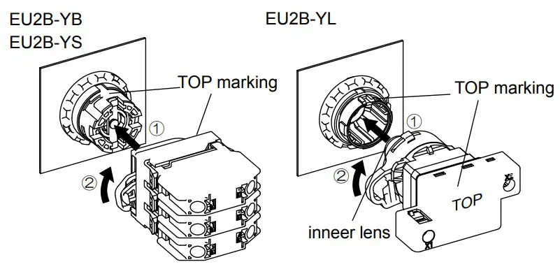
Note: When installing the lamp unit, check that the inner lens is not loose.
Note: The contact block adapters for emergency stop switches cannot be used for pushbutton, selector and key selector switches.
<Removing the Contact block.>
To remove the contact block, insert a flat screwdriver under the latch of the contact block adapter and disengage the latch. (See the figure below)
Note: When reinstalling the contact block after maintenance or wiring, make sure that the contact configuration is correct. Installing the contact block in the incorrect position or incomplete installation may cause malfunction of the switch.

<Installing the Contact block>
Before installing the contact block, remove the contact block adapter from the operator, and install the contact block on the contact block adapter definitely.
Note: Do not install the contact block with the control block adapter attached to the operator. Otherwise, malfunction may result.
- Panel thickness: 1.0 to 4.5 mm
Wiring
- Applicable wires
Stranded wire: 1.25 to 2.5 mm2, solid wire: φ1.2 to φ1.6 mm (AWG16 to 14) (Note) Do not connect more than 2 wires to the same terminal. - Applicable crimping terminal
(Note) Do not use ring terminals for EU2B control units with IP20 protection.
(Note) When connecting 2 ferrules to the EU2B control unit, use ferrules without insulating sheath.
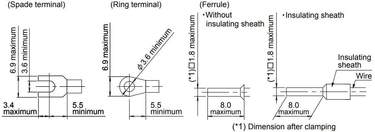
- Recommended crimping terminal (WAGO)
Ferrule with insulating sheath: 216-204,
Ferrule without insulating sheath: 216-104, Crimping plier: 206-204
- Recommended crimping terminal (WAGO)
- Recommended tightening torque EU2B control units (M3.5) : 1.0 to 1.3Nm
WARNING:
Incorrect wiring may cause fire hazard. Observe the following conditions.
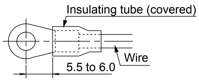
- Be sure to install an insulating tube on the crimping terminal or the crimping terminal with insulation.
- When connecting solid wires or stranded wires directly, strip the insulation as mentioned below and insert the wire all the way in. EU2B Control units: 8.6 mm maximum
- When using stranded wires, make sure that there are no wire whiskers.
- Make sure that the spade and ferrules are inserted all the way in.
Commissioning
Before commissioning, ensure that:
- wires are correctly connected,
- the EU2B control unit is installed been fitted in accordance with this instruction manual,
- the EU2B control unit is not damaged.
Maintenance and Inspection
- Notes for inspecting the EU2B control units
- 1) Observe the laws and regulations set by each country.
- 2) Never disassemble the control units.
- 3) Do not use tools that cause impact sparks during maintenance and inspection.
- 4) When using measuring devices, use explosion-protected types.
- 5) Do not carry out under the explosion-hazardous environment.
- Maintenance and inspection
Perform daily or periodical maintenance and inspection for items listed in the below table.
Table. Maintenance and Inspection Example
| Inspection Items | Inspection method | Inspections | Actions |
| Unit | Visual |
|
|
| Packings | Visual |
|
|
| Terminal | Visual Tactile |
|
|
Accessories and spare parts
- Color buttons for Pushbutton switchᲴ
Flush/ HW1A-B1š, Extended/ HW1A-B2š, Mushroom/ HW1A-B4š
Note: Specify a color code in place of š. ( R: red, G: green, B: black, Y: yellow, W: white, S: blue ) - Color lens for Pilot light: EU9Z-Lš (Install tool TW-KC1)
Note: Specify a color code in place of š. ( R: red, G: green, A: amber, Y: yellow, W: white, S: blue )
Note: Use a white (W) color lens for pure white illumination. - Nameplate: EU9Z-NMš
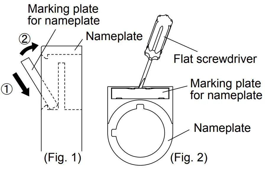
Marking plate for nameplate: EU9Z-NPšCode( ☐ ) Legend 0 (blank) 1 ON 2 OFF 3 START 4 STOP 31 OFF-ON 35 HAND-AUTO 53 HAND-OFF-AUTO - Installing the marking plate to a nameplate (See fig. 1)
- Removing the marking plate from a nameplate (See fig. 2)
To remove the marking plate, insert a flat screwdriver between the marking plate and nameplate.
- When using a nameplate, the mounting panel thickness is decreased by 1.5 mm. 1.0 to 3.0 mm
- Nameplate sticker for Emergency stop switch: EU9Z-NVS27 Legend “EMERGENCY STOP”
- Padlocking cover: for Emergency stop switch/ EU9Z-PCE for Pushbutton switch (Flush, Extended) and Key selector switch/ EU9Z-PC
- When using a padlocking cover, the mounting panel thickness is decresed by 1.5 mm. (1.0 to 3.0 mm)
- When using a padlocking cover, the mounting panel thickness is decresed by 1.5 mm. (1.0 to 3.0 mm)
- Mounting hole plug: EU9Z-BP (See the right figures)
(Note) Only use accessories and spare parts specified by IDEC. Use of any other accessories and spare parts will void the warranty
Disposal
Observe the laws and regulations set by each country concerning refuse disposal.
Specifications and other descriptions in this manual are subject to change without notice.
Draw. No. B-1044C
Feb. 3, 2012
6-64 Nishimiyahara 2-chome, Yodogawa-ku, Osaka, 532-0004, Japan