BuliBoao 22 Wheel Fitment Tool
Contents
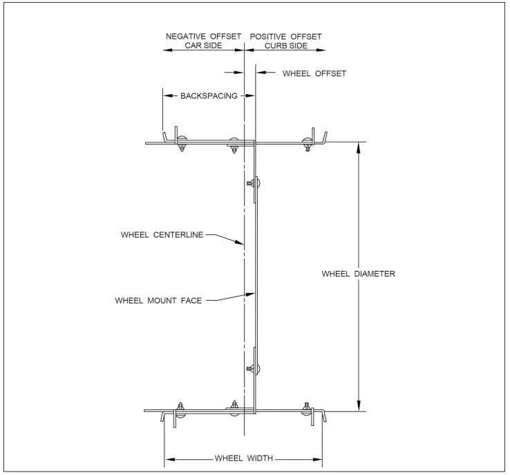
Wheel Dimensions
Wheel dimensions using WheelwiseTM Tool
ASSEMBLY INSTRUCTIONS
- Assemble the extensions and tire clamps as shown but leave the wing nuts loose.
Repeat for the other assembly. - Below is a chart giving recommendations for wheel width compared to tire width. Using a tape measure set the desired wheel width and tighten the middle wing nut. Repeat for the other assembly.
Wheel Width Minimum Tire Width Ideal Tire Width Maximum Tire Width 7inches 195mm 205or215mm 225mm 7-1/2 inches 205mm 215or225mm 235mm 8inches 215mm 225or235mm 245mm 8-1/2 inches 225mm 235or245mm 255mm 9inches 235mm 245or255mm 265mm 9-1/2 inches 245mm 255or265mm 275mm 10 inches 255mm 265or275mm 285mm 10-1/2 inches 265mm 275or285mm 295mm 11 inches 275mm 285or295mm 305mm 11-1/2 inches 285mm 295or305mm 315mm 12 inches 295mm 305or315mm 325mm 12-1/2 inches 305mm 315or325mm 335mm 13inches 315mm 325or335mm 345mm 13-1/2 inches 325mm 3_35 or 345 mm 355mm 14 inches 335mm 345or355mm 365mm 14-1/2 inches 345mm 355or365mm 375mm lSinches 355mm 365or375mm 385mm 15-1/2 inches 365mm 375or385mm 395mm 16 inches 375mm 385or395mm 405mm 16-1/2 inches 385mm 395or405mm 415 mm 17inches 395mm 405or415mm 425mm - Install the extensions onto the tire 180 degrees from each other. Slide the tire clamps against the tire and tighten the wing nuts. Remove the center carriage bolts and wing nuts after the clamps are tight against the tire.
- Assemble the center section as shown below at your desired wheel diameter.
- Insert the center section at an angle and rotate until perpendicular to the extensions.
- Insert the carriage bolts and wing nuts attaching the center section and the extensions. Slide the center section to your desired backspacing and tighten the wing nuts. Measure from the inside of the tire to the edge of the WheelWise™ Tool on both sides to ensure it is centered in the tire.
- Support the vehicle with jack stands. Install the WheelWise™ Tool and tire assembly onto the vehicle. Check tire and wheel clearances by turning the wheel left to right and raising and lowering the suspension. Adjust the backspacing as needed to gain proper clearance.
- Once you have gained proper clearance remove the assembly.
Note the following:
i. Bolt Hole Pattern (Etched on the hub mount plate)
ii. Wheei Diameter (Etched on the angles)
iii. Wheel Width (Dimension from step 2)
iv. Wheel Backspacing (Measure as shown on page 3)
Example:
Taking our sample 9 inch wheel width measurement from the tool and adding 1 inch to account for wheel flange thickness, our overall wheel width is 10 inches. This makes our wheel centerline dimension to be 5 inches (10 divided by 2= 5). Measuring the backspacing as indicated above, we have a measurement of 5-3/4-inches. At this point we’ve taken two simple measurements and we have everything we need to calculate offset with some simple math.
Formula:
Backspace – wheel centerline = offset
Any fractional answer ( the 3/ 4 in the backspace) needs to be converted to a decimal equivalent by division first.
3 divided by 4 = . 750
Our wheel sample: 5.750 – 5 = .750-inch
However, since offset is stated in millimeters, we have one more calculation to run. There are 25.4 millimeters in an inch, so multiply your answer from your first formula by 25.4 to obtain your offset in millimeters .
750 x 25.4 = 19.05mm positive offset
(wheel mounting surface towards the outside of the wheel)
If the backspace measurement is smaller than the wheel centerline measurement, your offset would be negative (wheel mounting surface towards the inside of the wheel}.
The deeper, more concave appearance you want in your wheel face, the more negative your offset needs to be.
Conversely, a more positive offset will provide for a flatter wheel face appearance. Finally, know that a positive offset provides for more backspacing, while a negative offset reduces backspacing.
Quick Reference Offset Chart
Backspacing (in inches)
| Wheel Width | 3.25 | 3.5 | 3.75 | 4.00 | 4.25 | 4.50 | 4.75 | 5.00 | 5.25 | 5.50 | 5.75 | 6.00 | |
| 7inches | -19 | -12 | -6 | 0 | 6 | 12 | 19 | 25 | 32 | 38 | 44 | 51 | |
| 7-1/2 inches | -25 | -19 | -12 | -6 | 0 | 6 | 12 | 19 | 25 | 32 | 38 | 44 | |
| 8 inches | -32 | -25 | -19 | -12 | -6 | 0 | 6 | 12 | 19 | 25 | 32 | 38 | |
| 8-1 /2 inches | -38 | -32 | -25 | -19 | -12 | -6 | 0 | 6 | 12 | 19 | 25 | 32 | |
| 9 inches | -44 | -38 | -32 | -25 | -19 | -12 | -6 | 0 | 6 | 12 | 19 | 25 | |
| 9-1 /2 inches | -51 | -44 | -38 | -32 | -25 | -19 | -12 | -6 | 0 | 6 | 12 | 19 | |
| 10 inches | -57 | -51 | -44 | -38 | -32 | -25 | -19 | -12 | -6 | 0 | 6 | 12 | |
| 10-1 /2 inches | -63 | -57 | -51 | -44 | -38 | -32 | -25 | -19 | -12 | -6 | 0 | 6 | |
| 11 inches | -69 | -63 | -57 | -51 | -44 | -38 | -32 | -25 | -19 | -12 | -6 | 0 | |
| 11-1 /2 inches | -75 | -69 | -63 | -57 | -51 | -44 | -38 | -32 | -25 | -19 | -12 | -6 | |
| 12 inches | · 81 | -75 | -69 | -63 | -57 | -51 | .44 | -38 | · 32 | -25 | -19 | -12 | |
| 12-1 /2 inches | -88 | -81 | -75 | -69 | -63 | -57 | -51 | -44 | -38 | -32 | -25 | -19 | |
| 13 inches | -95 | -88 | -81 | -75 | -69 | -63 | -57 | -51 | -44 | -38 | -32 | -25 | |
| 13-1 /2 inches | -101 | -95 | -88 | -81 | -75 | -69 | -63 | -57 | -51 | -44 | -38 | -32 | |
| 14 inches | -108 | -101 | -95 | -88 | -81 | -75 | -69 | -63 | -57 | -51 | -44 | -38 | |
| 14-1/2 inches | -114 | -108 | -101 | -95 | -88 | -81 | -75 | -69 | -63 | -57 | -51 | -44 | |
| 15 inches | -120 | -114 | -108 | -101 | -95 | -88 | -81 | -75 | -69 | -63 | -57 | -51 | |
| 15-1/2 inches | -127 | -120 | -114 | -108 | -101 | -95 | -88 | -81 | -75 | -69 | -63 | -57 | |
| 16inches | -133 | -127 | -120 | -114 | -108 | -101 | -95 | -88 | -81 | -75 | -69 | -63 | |
| 16-1/2 inches | -139 | -133 | -127 | -120 | -114 | -108 | -101 | -95 | -88 | -81 | -75 | -69 | |
| 17 inches | -146 | -139 | -133 | -127 | -120 | -114 | -108 | -101 | -95 | -88 | -81 | -75 |
DIMENSIONS
While performing the math shown previously on page 8 will determine the most accurate offset measurement, this reference chart will allow you to see the changes in offset and backspacing as one affects the other.
(Offset values listed in millimeters)