Danfoss CDS 203 Drive Superheat Controller Instruction Manual

Important Safety Information
Please read the IMPORTANT SAFETY INFORMATION below, and all Warning and Caution information elsewhere.
 Danger: Indicates a risk of electric shock, which, if not avoided, could result in damage to the equipment and possible injury or death.
System design, installation, commissioning and maintenance must be carried out only by personnel who have the necessary training and experience. They must carefully read this safety information and the instructions in this Guide and follow all information regarding transport, storage, installation and use of the CDS 203, including the specified environmental limitations.
Do not perform any flash test or voltage withstand test on the CDS 203. Any electrical measurements required should be carried out with the CDS 203 disconnected.
Internal surge arrestors are fitted, intended to protect against damage due to mains borne spikes, which will result in the product failing the flash test.
Electric shock hazard! Disconnect and ISOLATE the CDS 203 before attempting any work on it. High voltages are present at the terminals and within the drive for up to 10 minutes after disconnection of the electrical supply. Always ensure by using a suitable multimeter that no voltage is present on any drive power terminals prior to commencing any work.
Where supply to the drive is through a plug and socket connector, do not disconnect until 10 minutes have elapsed after turning off the supply.
Ensure correct earthing connections and cable selection as per defined by local legislation or codes.
The drive may have a leakage current of greater than 3.5mA; furthermore the earth cable must be sufficient to carry the maximum supply fault current which normally will be limited by the fuses or MCB. Suitably rated fuses or MCB should be fitted in the mains supply to the drive, according to any local legislation or codes.
Do not carry out any work on the drive control cables whilst power is applied to the drive or to the external control circuits.
Within the European Union, all machinery in which this product is used must comply with Directive 98/37/EC, Safety of Machinery. In particular, the machine manufacturer is responsible for providing a main switch and ensuring the electrical equipment complies with EN60204-1.
The level of integrity offered by the CDS 203 control input functions – for example stop/start, forward/reverse and maximum speed, is not sufficient for use in safety-critical applications without independent channels of protection.
All applications where malfunction could cause injury or loss of life must be subject to a risk assessment and further protection provided where needed.
The driven motor can start at power up if the enable input signal is present.
The STOP function does not remove potentially lethal high voltages. ISOLATE the drive and wait 10 minutes before starting any work on it. Never carry out any work on the Drive, Motor or Motor cable whilst the input power is still applied.
The CDS 203 can be programmed to operate the driven motor at speeds above or below the speed achieved when connecting the motor directly to the mains supply. Obtain confirmation from the manufacturers of the motor and the driven machine about suitability for operation over the intended speed range prior to machine start up.
Do not activate the automatic fault reset function on any systems whereby this may cause a potentially dangerous situation.
CDS 203 are intended for indoor use only.
When mounting the drive, ensure that sufficient cooling is provided. Do not carry out drilling operations with the drive in place, dust and swarf from drilling may lead to damage.
The entry of conductive or flammable foreign bodies should be prevented. Flammable material should not be placed close to the drive.
Relative humidity must be less than 95% (non-condensing).
Ensure that the supply voltage, frequency and no. of phases (1 or 3 phase) correspond to the rating of the CDS 203 as delivered. Never connect the mains power supply to the Output terminals U, V, W.
Do not install any type of automatic switchgear between the drive and the motor. This may cause the drive protection to activate, resulting in a trip and loss of operation.
Wherever control cabling is close to power cabling, maintain a minimum separation of 100 mm and arrange crossings at 90 degrees.
Ensure that all terminals are tightened to the appropriate torque setting.
Do not attempt to carry out any repair of the CDS 203. In the case of suspected fault or malfunction, contact your local Danfoss Compressor Sales Partner for further assistance.
Product Introduction
The product range has been specifically designed for OEM and machine-builders alike with through panel mounting and cold-plate technology options available. The drive has no direct keypad/display but shows drive status with two status indicating LEDs on the front.
Identifying the Drive by Model Number
Each drive can be identified by its model number, shown below. The model number is on the shipping label, the drive rating label on the upper surface of the drive and on the front surface on the product identifier. The model number includes the drive and factory fitted options.
 Model Variants
| 200 – 240V +/-10% Single Phase Input |
| Model Code |
Frame |
kW |
HP |
Amps |
| CDS203-22P1K5-1FH11 |
2 |
1.5 |
2 |
7.0 |
CDS203-22P3K0-1FH21
CDS203-22P3K0-1FH31 |
2 |
3 |
3 |
12.0 |
| CDS203-22P4K0-1FH41 |
2 |
4 |
5.5 |
16.0 |
| 380 – 480V +/-10% Three Phase Input |
| Model Code |
Frame |
kW |
HP |
Amps |
| CDS203-24P5K5-3FH31 CDS203-24P5K5-1FH41 |
2 |
5.5 |
7.5 |
14 |
CDS203-24P11K-3FH51
CDS203-24P11K-3FH61 |
2 |
11 |
15 |
24 |
Installation
Mechanical Installation
General
-
- The Danfoss CDS 203 has been designed to be installed in a suitable enclosure. The drive can be through panel mounted or mounted directly onto the back of a panel using the appropriate mounting kit.
- Using the drive as a template, or the dimensions shown below, mark the locations for drilling.
-
- Ensure that when mounting locations are drilled, the dust from drilling does not enter the drive.
-
- Mount the drive to the cabinet backplate using suitable mounting screws.
- Position the drive, and tighten the mounting screws securely.
- The front of the drive is IP20 and must be installed in a pollution degree 1 or 2 environment only.
- In any environments where the conditions require it, the enclosure must be designed to protect the drive against ingress of airborne dust, corrosive gases or liquids, conductive contaminants (such as condensation, carbon dust, and metallic particles) and sprays or splashing water from all directions.
- Enclosures should be made from a thermally conductive material.
- Do not mount flammable material close to the CDS 203.Ensure that the minimum cooling air gaps, as detailed in section Ventilation and clearance.
Before Installation
-
- Carefully Unpack the CDS 203 and check for any signs of damage. Notify the shipper immediately if any exist.
-
- Check the drive rating label to ensure it is of the correct type and power requirements for the application.
- To prevent accidental damage always store the CDS 203 in its original box until required. Storage should be clean and dry and within the temperature range –40°C to +70°C.
Drive Dimensions
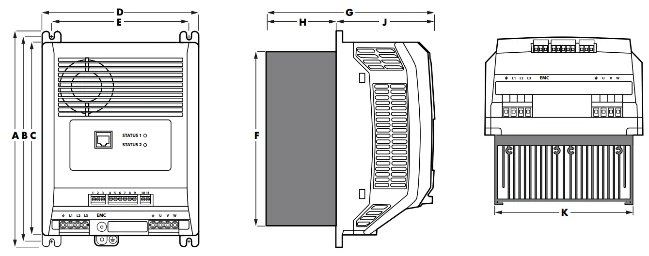
| A |
B |
C |
D |
E |
F |
G |
H |
J |
K |
| mm |
in |
mm |
in |
mm |
in |
mm |
in |
mm |
in |
mm |
in |
mm |
in |
mm |
in |
mm |
in |
mm |
in |
| 226.3 8.9 |
215.2 |
8.5 |
201.4 7.9 |
165.3 |
6.5 |
144.8 5.7 |
182 |
7.2 |
177 6.96 |
71.7 |
2.82 |
104.4 4.11 |
145 |
5.7 |
| Weights |
| All 400V drives with Heatsink |
3.05kg |
| 230V PFC Heatsink (7/12A) |
3.4kg |
| 230V PFC Heatsink (16/20A) |
3.74kg |
Ventilation and Clearance
In order for the drive to maintain it’s temperature, a minimum clearance is required around the drive as shown in the diagram below:

| W |
X |
Y |
Z* |
| mm |
in |
mm |
in |
mm |
in |
mm |
in |
| 20 0.787 |
78 |
3.07 |
10 0.394 |
100 |
3.94 |
NOTE Value ‘Z’ is not applicable to the coldplate variant. These dimensions are the absolute minimum recommended clearances to allow sufficient air flow. The enclosure itself must be significantly wider or taller than the values given above in at least one direction.
Through panel mounting
Through panel mounting is the most efficient installation in terms of both panel space and thermal management.
With the heatsink protruding through the back of the electrical panel, the heat generated by the drive will be exhausted outside of the electrical panel.
| A |
B |
C |
D |
E |
F |
G |
H |
J |
| mm |
in |
mm |
in |
mm |
in |
mm |
in |
mm |
in |
mm |
in |
mm |
in |
mm |
in |
mm |
in |
| 226.3 8.9 |
15.6 |
0.61 |
184 7.24 |
15.6 |
0.61 |
165.3 6.5 |
147 |
5.78 |
177 6.96 |
71.7 |
2.82 |
104.4 4.11 |
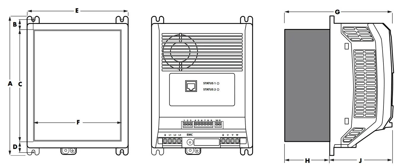
Panel mounting (with the panel mounting kit)
If the installation does not lend itself to through panel mounting, the drive can be mounted to a back-plate of a panel using the optional panel mounting kit.
| A |
B |
C |
D |
E |
F |
G |
| mm |
in |
mm |
in |
mm |
in |
mm |
in |
mm |
in |
mm |
in |
mm |
in |
| 215.2 8.47 |
42.7 |
1.68 |
80 3.15 |
165.3 |
6.5 |
73.7 2.9 |
228 |
8.98 |
179 7.04 |

Panel mounting the cold-plate variant
The CDS 2003 is also available without a heatsink but with a cold plate that needs to be mounted onto a heat transfer surface, removing the drive losses and maintaining the cold plate temperature.
| A |
B |
C |
D |
E |
F |
G |
H |
J |
| mm |
in |
mm |
in |
mm |
in |
mm |
in |
mm |
in |
mm |
in |
mm |
in |
mm |
in |
mm |
in |
| 226.3 8.9 |
215.2 |
8.5 |
201.4 7.9 |
165.3 |
6.5 |
90 3.5 |
37.7 |
1.48 |
113.9 4.48 |
104.4 |
4.11 |
9.5 0.37 |

| Tightening Torques |
|
Required Torque |
| Control Terminals |
0.5 Nm |
4.5 lb-in |
| Power Terminals |
1 Nm |
9 lb-in |
| Weights |
| All 400V Cold plate Drive |
2.03kg |
| 230V PFC Cold plate Drives (7A & 12A) |
2.4kg |
| 230V PFC Cold plate Drives (16A & 20A) |
2.74kg |
Connection Diagram
All power terminal locations are marked directly on the product with AC power input and motor connections located at the bottom of the unit.
Electrical Power Connections

Incoming Power Connection
Cable Selection
- For 1 phase supply, the mains power cables should be connected to L1/L, L2/N.
- For 3 phase supplies, the mains power cables should be connected to L1, L2, and L3. Phase sequence is not important.
- The cables should be dimension according to any local codes or regulations. Maximum dimensions are given in section 6.1. Detailed Product Rating Tables .
Protective Earth Conductor
- The cross-sectional area of the PE Conductor must be at least equal to that of the incoming supply conductor and connected to the drives main earth terminal.
Fuse / Circuit Breaker Selection
-
- Suitable fuses to provide wiring protection of the input power cable should be installed in the incoming supply line, according to the data in section 6.1. Detailed Product Rating Tables on page 16. The fuses must comply with any local codes or regulations in place. In general, type gG (IEC 60269) or UL type J fuses are suitable; however in some cases type aR fuses may be required. The operating time of the fuses must be below 0.5 seconds.
- Where allowed by local regulations, suitably dimensioned type B MCB circuit breakers of equivalent rating may be utilised in place of fuses, providing that the clearing capacity is sufficient for the installation.
- The maximum permissible short circuit current at the CDS 203 Power terminals as defined in IEC60439-1 is 100kA.
Motor Connection
-
- The motor should be connected to the CDS 203 U, V, and W terminals using a suitable 3 or 4 core cable. Where a 3 core cable is utilised, with the shield operating as an earth conductor, the shield must have a cross sectional area at least equal to the phase conductors when they are made from the same material. Where a 4 core cable is utilised, the earth conductor must be of at least equal cross sectional area and manufactured from the same material as the phase conductors.
- The motor earth must be connected to one of the CDS 203 earth terminals.
- Maximum permitted motor cable length for all models: 10 metres shielded, 20 metres unshielded.
Power Connections
| 230V Single Phase Variants |
| E |
Power Earth / Ground |
| L |
L1 (200VAC) |
| N |
Neutral |
| E |
Power Earth / Ground |
| U |
Motor U Phase |
| V |
Motor V Phase |
| W |
Motor W Phase |
| 400V 3-Phase Variants |
| E |
Power Earth / Ground |
| L1 |
Supply L1 |
| L2 |
Supply L2 |
| L3 |
Supply L3 |
| E |
Power Earth / Ground |
| U |
Motor U Phase |
| V |
Motor V Phase |
| W |
Motor W Phase |

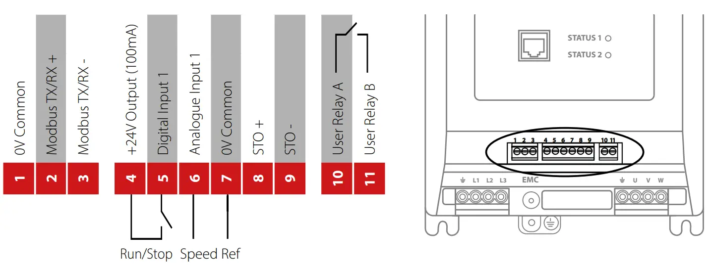
Control Wiring
The CDS 203 has pluggable control terminals to support easy installation.
There are three pluggable control terminal blocks split into:
-
- Serial Communications (T1-T3)
- Inputs (T5 – T9)
- Output Relay (T10 – T11)
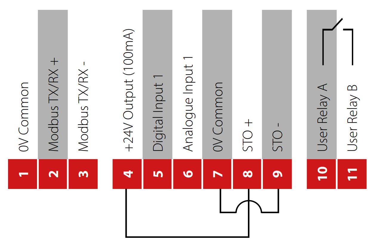
Safe Torque Of
For information covering the STO function refer to section 3.3.4 in the main user guide.
The STO input is a hardware enable for the drive. If your application does not require the Safe Torque Off function, it will be necessary to link terminal 4 to terminal 8 and separately terminal 7 to terminal 9 as per the diagram below:
Set-up and Operation
Basic Checks Before Commissioning
Please check that the drive and compressor are matching by checking both drive and compressors label – the compressor model is indeed mentioned on the drive label for an easy check.
Access to Parameters
The drive parameters can be accessed via one of the following methods:
-
- Mod Bus Communications
- CDS203 LCP
- CoolSetting – Drive Setup Software
Operating Limits and Ramp Rates
| Par. |
Mod bus Address |
Description |
Def |
Min |
Max |
Unit |
R/W |
| 1-01 |
101 |
Maximum Motor Speed |
60 |
P1-02 |
500 |
Rps |
R/W |
| 1-02 |
102 |
Minimum Motor Speed |
20 |
0 |
P1-01 |
Rps |
R/W |
| 1-03 |
103 |
Acceleration Ramp Time from 0rps to Rated Speed |
5.0 |
0 |
6000 |
s |
R/W |
| 1-04 |
104 |
Deceleration Ramp Time from Rated Speed to 0rps |
5.0 |
0 |
6000 |
5 |
R/W |
| 5-06 |
506 |
Motor Switching Frequency (24 x max frequency) |
DD |
DD |
DD |
kHz |
R/W |
| 5-07 |
507 |
Maximum Torque / Current Limit |
110 |
20 |
130 |
% |
R/W |
| 5-18 |
518 |
Maximum Peak Output Current |
Drive rating dependant Apk |
|
|
|
R/W |
Start-up Sequence
| Par. |
Modbus Address |
Description |
Def |
Min |
Max |
Unit |
R/W |
| 2-01 |
201 |
Start Speed 1 |
37 |
P1-02 |
|
Rps |
R/W |
| 2-02 |
202 |
Start Speed 1 Time |
60 |
0 |
600 |
5 |
R/W |
| 2-03 |
203 |
Start Speed 1 Acceleration Ramp Rate 0rps to Start Speed 1 |
30 |
0 |
6000 |
5 |
R/W |
| 2-04 |
204 |
Start Speed 2 |
0 |
P1-02 |
|
Rps |
R/W |
| 2-05 |
205 |
Start Speed 2 Time |
0 |
0 |
600 |
5 |
R/W |
| 2-06 |
206 |
Start Speed 2 Acceleration Ramp Rate 0rps to Start Speed 2 |
0 |
0 |
6000 |
5 |
R/W |
| 2-07 |
207 |
Start Speed 3 |
0 |
P1-02 |
|
Rps |
R/W |
| 2-08 |
208 |
Start Speed 3 Time |
0 |
0 |
600 |
5 |
R/W |
| 2-09 |
209 |
Start Speed 3 Acceleration Ramp Rate 0rps to Start Speed 3 |
0 |
0 |
6000 |
5 |
R/W |
If the start-up sequencing (or part of the start-up sequencing) is not required, set that Start Speed Time to 0s to disable that function. e.g. if you want to have one part of the start up sequence, set Start Speed 1 (P2-01) to the desired speed in rps, set the time for the motor to sit at speed 1 in P2-02 and set the desired ramp rate in P2-03 – then ensure that P2-05 and P2-08 are both set to 0s. On start-up in this example, the drive will ramp the speed set in P2-01 using the ramp rate set in P2-03 for a duration set in P2-02 before then following the chosen speed reference.
NOTE The ramp rates here are entered in seconds per rated speed of the motor (e.g. 5.0s to go from 0rps to 60 rps) where 60 rps is the compressor rated speed..
Re-start Blocking
| Par. |
Modbus Address |
Description |
Def |
Min |
Max |
Unit |
R/W |
| 2-10 |
210 |
Minimum Off Time |
180 |
0 |
6000 |
5 |
R/W |
| 2-11 |
211 |
Minimum On Time |
180 |
0 |
6000 |
5 |
R/W |
| 2-12 |
212 |
Re-start Delay (Start-to-start Delay) |
600 |
0 |
6000 |
5 |
R/W |
| 2-13 |
213 |
Re-start Function |
10 |
0 |
Auto-10 |
– |
R/W |
NOTE Setting the minimum on time can mean that the drive will continue to run when the stop command is given. Removal of the STO signal will override any other command.
Control Mode
| Par. |
Modbus Address |
Description |
Def |
Min |
Max |
Unit |
R/W |
| 1-11 |
111 |
Command Source
0: Modbus Mode
- Terminal Control
- Terminal Control (AI1 Start)
- User PID Mode
|
1- Terminal |
0 |
3 |
– |
R/W |
| 1-05 |
105 |
5 Stop Mode
0: Ramp to Stop
- Coast to Stop
- AC Flux Braking (IM Motor only)
- Ramp to Minimum Speed then Coast to Stop
|
1 |
0 |
3 |
– |
R/W |
The primary command source setting in P1-11 makes a significant difference to how the drive is operated or controlled. The following table provides an overview of how the control commands vary for each setting.
| P1-11 |
Drive Enable |
Run/Stop |
Speed Ref. |
Ramps |
Fault reset |
Crankcase Heating |
| 0 – Modbus |
Safety (STO) |
Modbus |
Modbus |
Parameters |
DI1 / Modbus |
Modbus |
| 1 – Termina |
Safety (STO) |
DI1 |
AI1 |
Parameters |
DI1 |
STO / Modbus |
| 2 – Terminal AI Start |
Safety (STO) |
AI1>10% / AI1<5% |
AI1 |
Parameters |
DI1 |
DI1 / Modbus |
| 3 – User PI |
Safety (STO) |
DI1 |
PI Output |
Parameters |
DI1 |
STO / Modbus |
Diagnostics
Trips
| Fault Code |
No. |
Description |
Suggested Remedy |
 |
00 |
Drive output fault |
No fault in trip log – no problem with the drive |
 |
03 |
Instantaneous over current |
High current from either – short-circuit on the drive output / acceleration ramps too short / incorrect motor data.
NOTE Setting the maximum peak motor current too low in P5-18 could also lead to this trip. |
 |
04 |
Motor Thermal Overload (I2t) |
Drive has been delivering more than the configured motor rated current for a period of time – check the operating point of the compressor |
 |
05 |
Power stage trip |
Hardware fault, contact the supplier of the drive |
 |
06 |
Over voltage on DC bus |
DC Bus Overvoltage from either – the supply voltage is too high, a spike in the supply voltage, motor instability, try setting P1-05 = 3 |
 |
07 |
Under voltage on DC bus |
Usually caused by the supply voltage dropping too low – check connections and voltage at the drive terminals |
 |
08 |
Heatsink over
temperature |
Check the ambient temperature, check that the ventilation is not restricted, check the cooling system for the coldplate version |
 |
09 |
Under temperature |
Drive heatsink temperature is too low |
 |
10 |
Factory Default parameters have been loaded |
Warning to advise that the drive has been returned to factory defaults |
 |
11 |
Safety circuit momentarily opened during drive running |
Check the wiring of the STO circuit and any switches or devices within that circuit. Ensure that any intermediate devices are not activating momentarily during drive operation. |
 |
12 |
Optibus comms loss |
Loss of communications between drive and remote keypad or PC tools |
 |
13 |
DC bus ripple too high |
Check for supply phase imbalance or phase loss |
 |
14 |
Input phase loss trip |
Input phase loss trip – similar to FLt.dc above |
 |
15 |
Instantaneous over
current on drive output |
Hardware overcurrent on drive output – similar to O-I trip above |
 |
16 |
Faulty thermistor on
heatsink |
If the drive heatsink temperature is within limits, contact the supplier of the drive |
 |
17 |
Internal memory fault
(IO) |
If not coinciding with a firmware upgrade procedure, contact the supplier of the drive |
 |
18 |
4-20mA Signal Lost |
Analogue input configured for 4-20mA but less than 3mA detected on drive terminals |
 |
19 |
Internal memory fault
(DSP) |
If not coinciding with a firmware upgrade procedure, contact the supplier of the drive |
 |
20 |
User Default Parameters Loaded |
User Default Parameters Loaded |
 |
21 |
Motor PTC thermistor trip |
Drive configured to monitor motor temperature through the PTC and resistance increases above 2.5k |
 |
22 |
Cooling Fan Fault |
Drive cooling fan not running at demanded speed – check for any blockages in the cooling fan |
 |
23 |
Environmental temperature too high |
Check ambient temperature and ventilation system |
 |
26 |
Drive output fault |
Check for wiring faults, loose connections or badly terminated cables between the drive and the motor |
 |
29 |
Safety circuit momentarily opened during drive runningSlow rising edge on 24V supply
Safety input circuit error |
Check the wiring of the STO circuit and any switches or devices within that circuit. Ensure that any intermediate devices are not activating momentarily during drive operation.Can happen if an external 24V supply is used and the voltage ramps up slowly on power-up. Could also happen if the drive 24V rail is overloaded and collapses momentarily, check the loading of the 24V rail and all control connections.
Contact the supplier of the drive for further advice |
 |
31 |
Locked Rotor |
A speed error has been detected (Locked Rotor) |
 |
40 |
Measured motor stator resistance varies between phases |
Check the motor wiring, disconnect the drive and measure the phase to phase resistance from the motor cable |
 |
41 |
Measured motor stator
resistance is too large |
Check the motor wiring, disconnect the drive and measure the phase to phase resistance from the motor cable and refer to motor datasheet |
 |
42 |
Measured motor
inductance is too low |
Check the motor wiring |
 |
43 |
Measured motor
inductance is too large |
Check the motor wiring |
 |
44 |
Measured motor parameters are not convergent |
Check the motor wiring |
 |
49 |
Motor output phase loss |
Check the motor wiring |
 |
50 |
Modbus comms loss fault |
Check the Modbus wiring, ensure that the 0V common is used, ensure that the communication wiring is kept away from any power wiring |
|
|
|
|
Status LED Indication
Two LEDs are used to indicate the drive status as follows:
| Drive Status |
LED 1 Status |
LED 2 Status |
| Green |
Red |
Yellow |
| Stop |
Slow flashing |
Off |
Off |
| Inhibit |
Slow Flashing |
Off |
Slow Flashing alternate |
| Running |
Constant On |
Off |
Slow flashing if in overload |
| Standby |
Constant On |
Off |
Blink every 3s |
| Trip / Fault |
Off |
Constant On |
Off |
| Internal Comms Loss |
Off |
Blink every 3s |
Off |
| Oil Return Active |
Constant On |
Off |
Fast Flashing Yellow |
| DSP Firmware Upgrade |
All three LEDs lights up in order (Green->Yellow->Red->Yellow…) |
| IO Firmware Upgrade |
All LEDs on with weak light |
Technical Data
Detailed Product Rating Tables
| Part Number |
Power Rating |
Input Current |
Fuse or MCB (Type B) |
Max Input Cable Size |
Continuous Output Current |
Overload Output Current |
Maximum Output Cable Size |
Maximum Motor Cable Length |
| kW |
HP |
A |
Non UL |
UL |
mm2 |
awg |
A |
A |
mm2 |
awg |
m |
ft |
| CDS203-22P1K5-1FH11 |
1.5 |
2.0 |
8.9 |
16 |
15 |
16 |
6 |
7 |
9.1 |
6 |
10 |
10 |
33 |
| CDS203-22P3K0-1FH21 CDS203-22P3K0-1FH31 |
3.0 |
3.0 |
15.8 |
25 |
20 |
16 |
6 |
12 |
13.2 |
6 |
10 |
10 |
33 |
| CDS203-22P4K0-1FH41 |
4.0 |
5.5 |
21.3 |
25 |
25 |
16 |
6 |
16 |
20.8 |
6 |
10 |
10 |
33 |
| CDS203-22P1K5-1FC11 |
1.5 |
2.0 |
8.9 |
16 |
15 |
16 |
6 |
7 |
9.1 |
6 |
10 |
10 |
33 |
| CDS203-22P3K0-1FC21 CDS203-22P3K0-1FC31 |
3.0 |
3.0 |
15.8 |
25 |
20 |
16 |
6 |
12 |
13.2 |
6 |
10 |
10 |
33 |
| CDS203-22P4K0-1FC41 |
4.0 |
5.5 |
21.3 |
25 |
25 |
16 |
6 |
16 |
20.8 |
6 |
10 |
10 |
33 |
| CDS203-24P5K5-3FH31 CDS203-24P5K5-3FH41 |
5.5 |
7.5 |
12.0 |
16 |
35* |
6 |
10 |
14 |
18.2 |
6 |
10 |
10 |
33 |
| CDS203-24P11K-3FH51 CDS203-24P11K-3FH61 |
11.0 |
15.0 |
22.0 |
25 |
35* |
6 |
10 |
24 |
28.0 |
6 |
10 |
10 |
33 |
| CDS203-24P5K5-3FC31 |
5.5 |
7.5 |
12.0 |
16 |
35* |
6 |
10 |
14 |
18.2 |
6 |
10 |
10 |
33 |
| CDS203-24P11K-3FC51CDS203-24P11K-3FC61 |
11.0 |
15.0 |
0 22.0 |
25 |
35* |
6 |
10 |
24 |
28.0 |
6 |
10 |
10 |
33 |
NOTE Maximum permissible motor cable without the use of output filters is 10m with shielded cable and 20m with unshielded cable – for all ratings.
Input Power Supply Requirements
| Supply Voltage |
Supply Voltage 200 – 240 RMS Volts for 230 Volt rated units, + /- 10% variation allowed. 380 – 480 Volts for 400 Volt rated units, + / – 10% variation allowed. |
| Imbalance |
Maximum 3% voltage variation between phase – phase voltages allowed. All CDS 203 units have phase imbalance monitoring. A phase imbalance of > 3% will result in the drive tripping. |
| Frequency |
50 – 60Hz + / – 5% Variation. |
https://www.danfoss.com/en/about-danfoss/our-businesses/cooling/commercial-compressors/’