Contents
HB Products STG Opening-Leaking Safety Valve Detection Sensor

The STG Opening/Leaking Safety Valve Detection Sensor is adevice used to detect the opening or leakage of safety valves in industrial settings. The device is equipped with various features such as power supply from 18V to 30V, communication via Modbus RTU
RS485 protocol, relay output, 4-20mA analog output, 0-10V analog output, and overvoltage and overcurrent protection. The device is also ATEX certified: II 3G Ex ic mc IIA T4 Gc.
Product Dimensions
The STG device has a dimension of 82mm with a process connection of 1 G-F. The device is equipped with an M12-8 poles-IP67 connector for electrical connections.
Product Installation
The STG device must be installed at the outlet of a safety valve or on the general downstream manifold line in the case of a circuit with multiple valves. It is recommended to install one STG device for each valve or a small group to easily identify which valve has
opened. The device should be installed as close as possible to the safety valve to detect opening or leakage more quickly. The recommended installation positions are at 3 o’clock or 9 o’clock for downstream line installation. In case of installation on a
vertical pipe, STG can be placed along the whole circumference. The device should be installed at a maximum of 5 cm from the downstream line pipe and Teflon tape should be applied on the threaded connection.
Product Operation
When switched on, the device goes through an initialization phase identified by flashing signaling LEDs. Once finished, the LEDs will remain on steady with the color relating to the percentage of gas read by the sensor. The green LEDs indicate normal status, orange LEDs indicate warning status, and red LEDs indicate alarm status. Flashing red LEDs indicate an alarm due to low pressure. In case STG detects a contraindicated gas presence value during start-up, the device immediately switches to the alarm state.
Dimensions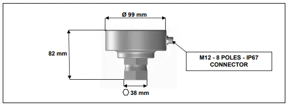
Installation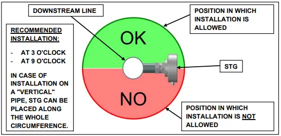
STG has to be installed at the outlet of a safety valve, or in the case of a circuit with multiple valves, it can be mounted on the general downstream manifold line.
To more easily identify which valve has opened, it is recommended to install No 1 STG device for each of them or at most for a small group, furthermore in order to detect the opening or leakage more quickly, it is advisable to install STG as close as possible to the safety valve.
It is recommended to install STG at a maximum of 5 cm from the downstream line pipe on which it is installed and to apply Teflon tape on the threaded connection.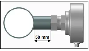
Features
| FEATURES | MODEL
STG-B STG-F |
|
| Power supply from 18V to 30V | √ | √ |
| Communication via Modbus RTU RS485 protocol | √ | √ |
| Relay output | √ | √ |
| 4-20mA analog output | X | √ |
| 0-10V analog output (maximum load 10mA) | X | √ |
| No 3 off two-color LED indicators for alarm signaling | √ | √ |
| Power LED indicator | √ | √ |
| Overvoltage and overcurrent protection | √ | √ |
| Degree of protection: IP 65 | √ | √ |
| Process connection: 1” G-F | √ | √ |
| ATEX certified: II 3G Ex ic mc IIA T4 Gc | √ | √ |
Electrical connections
The device interfaces with the outside world via a M12-8 poles connector:
| Power supply | PIN 1 | Vdc 0V |
| PIN 2 | Vdc +24V | |
| Communication Modbus RS485 | PIN 3 | Channel N |
| PIN 4 | Channel P | |
| Relay output | PIN 5 | NO |
| PIN 6 | C | |
| Analog output | PIN 7 | 0-10V |
| PIN 8 | 4-20mA |
Maximum values
| Supply voltage | Minimum 18Vdc, maximum 30 Vdc |
| Absorption current | 500mA |
| Relay output contacts voltage | 30Vdc or 30Vac |
| Relay output contacts current | 1A |
The device must be powered by a safe power source type SELV/PELV (Um = 30Vrms / 42Vdc).
Note: Um is the maximum voltage that can be applied to non-intrinsically safe connections without invalidating the type of protection, not to be confused with Vmax = 30Vdc which is the maximum rated voltage supported by the device.
Typical values of use
| Supply voltage | 24 Vdc |
| Absorption current | < 100mA |
Operation
When switched on, the device has an initialization phase in which it must settle at the value present in the environment: this phase is identified by a flashing of the signaling LEDs and ends when stop flashing. Once finished, the LEDs will remain on steady with the color relating to the percentage of gas read by the sensor. If during start-up, STG detects a contraindicated gas presence value, the device immediately switches to the “Alarm” state.
Green LEDs = “Normal” status
Orange LEDs = “Warning” status
Red LEDs = “Alarm” status
Flashing Red LEDs: Status of “Alarm” due to low pressure. This state indicates that there is a probable introduction of air and/or water from the abatement water tank into the refrigeration circuit.
Green LEDs flashing Red = Alarm occurred
Green LEDs with double flashing Red: Low pressure Alarm occurred
Green LEDs flashing = “Pre-Alarm” status. This status indicates that STG is detecting the presence of “dangerous” gas regardless of the threshold values set by the user. Parameter set in the factory, upon communication of the gas used (Ideal for explosive gases).
Furthermore, the following operating parameters can be adjusted via Modbus:
Modbus address (Slave ID): In case of installation of several STG devices, a different address must be assigned for each of them (Factory value = 1).
Warning: It is the warning percentage value. When this value is exceeded, STG converts the color of the LEDs to “orange”.
Alarm: It is the alarm percentage value. When this value is exceeded, STG converts the color of the LEDs to “red” and the relay will switch the output. Once normal operating conditions have been restored inside the drain pipe, STG will keep the alarm in memory by converting the LEDs to “green” interspersed with a “red” flash. This alarm can be reset using the appropriate Modbus address (see table “Modbus Configuration”).
Pressure Alarm: This is the pressure value to be entered in order to detect when, due to a leakage by a safety valve installed on the low pressure circuit (below the vacuum threshold), the introduction of air and/or water from of air and/or water from the abatement water tank into the refrigeration circuit. The default value set is 850 mbar (value that can be changed by the user), when this threshold is reached STG converts the color of the LEDs to “flashing red”. STG will keep the alarm in memory by converting the LEDs to “green” interspersed with a double “red” flash. This alarm can be reset using the appropriate Modbus address (see table “Modbus Configuration”)
Modbus setting
The device parameters and settings are fully configurable via Modbus RTU protocol, interfacing via RS485 serial; it is supplied already configured with these default values:
- Baudrate: 19200 bps
- Data bits: 8
- Stop bits: 1
- Parity: None
- Slave ID: 1
The device parameters can be set at any time via the Modbus interface, or via the Modbus/USB key and the free “STG Configurator” software available on the CO-REF website at the following address https://www.corefsrl.com/infodownload/.
For the list and related details, refer to the “Modbus Configuration” table.
Modbus configuration
|
Modbus Address |
Parameter & Register Name | No of 16bit regs |
Data Type |
Range |
Default value |
Read Write |
Unit |
Description |
| Setting parameters | ||||||||
|
7 |
Modbus slave ID |
1 |
1 byte |
[1 ‐ 247] |
1 |
R / W |
Modbus Slave ID, values outside the specified range are rejected | |
|
8 |
Serial Speed |
1 |
1 byte |
0 = 4800
1 = 9600 2 =19200 3 =38400 4 = 57600 |
2 |
R / W |
Modbus baudrate or Serial speed, Data bits: 8; Stop Bits: 1; Parity: None |
|
| Data parameters* | ||||||||
| 256
257 |
% GAS in the pipeline |
2 |
32 bit float | [0 ‐ 100] |
R |
% |
Instant GAS measurement e.g.: 20BC[LSB] ‐ 41A2[MSB] ‐>
20.266 % |
|
|
258 259 |
STG Temperature |
2 |
32 bit float |
[‐20 +50] |
R |
°C |
STG temperature measurement e.g.: E148[LSB] ‐ 41F6[MSB] ‐> 30.86°C | |
|
260 261 |
STG Pressure |
2 |
32 bit float |
[100 ‐ 1400] |
R |
mBar |
STG pressure measurement e.g.: 2000[LSB] ‐ 4478[MSB] ‐> 992.5mBar |
|
|
264 265 |
% Warning |
2 |
32 bit float |
[0 ‐ 100] |
5.0 |
R/W |
% |
When %GAS exceeds this value, STG will switch to “Warning” status |
|
266 267 |
% Alarm |
2 |
32 bit float |
[0 ‐ 100] |
10.0 |
R/W |
% |
When %GAS exceeds this value, STG will switch to “Alarm” status |
|
272 |
Alarm Detected |
1 |
Unit16 |
[0 ‐ 1] |
0 |
R/W |
bool |
In alarm situation the register is set to 1. If the device exits the alarm situation, this register remains at 1; a modbus writing
of 0 allows to reset the register. |
|
281 282 |
Pressure Alarm |
2 |
32 bit float |
[100 ‐ 1400] |
850 |
R/W |
mBar |
This register specifies a pressure value that generates an alarm, should the device measure an instantaneous pressure lower than that configured in this
register; an alarm is generated. |
|
283 |
Pressure Alarm Detected |
1 |
Unit16 |
[0 ‐ 1] |
0 |
R/W |
bool |
In alarm situation the register is set to 1. If the device exits the alarm situation, this register remains at 1; a modbus writing
of 0 allows to reset the register |
COMPONENTI PER LE REFRIGERAZIONE
- Via Don Gnocchi, 24
- 20042 Pessano con Bornago (MI)
- Tel. +39 02 95749478
- E-mail: [email protected]
- https://www.corefsrl.com