Installation Manual
High Efficiency Air Handlers
2-3-4-5 Ton
R-410A TXV Inside

NOTE: Appearance of unit may vary.
Installation must be performed in accordance with the requirements of NEC and CEC by authorized personnel only.
All phases of this installation must comply with National, State and Local Codes.
This document is customer’s property and is to remain with this unit. Please return it to customer with service information upon completion of work.
These instructions are intended as an assist to qualified and licensed personnel for proper installation, adjustment and operation of ECM air handler units. Read it thoroughly before attempting installation or service work. Failure to follow these instructions may result in fire, electrical shock, property damage, personal injury or death.
The instructions do not cover all variations in systems or provide for every possible contingency to be met in connection with the installation.
![]()
Contents
Safety
Read the following safety instructions before installing the unit or doing service work.
 WARNING may cause personal death or serious injury.
CAUTION may lead to injury or structural damage under some conditions.
WARNING
Disconnect all power to unit before installing or servicing. More than one disconnecting switch may be required to de-energize the equipment. Hazardous voltage can cause server personal injury or death.
Installation and maintenance must be performed by authorized personnel only.
Consumer service is recommended only for filter cleaning/replacement. Never operate the unit with the access panels removed.
Failure to inspect pipes or use proper service tools may result in equipment damage or personal injury.
if using existing refrigerant pipes, make sure that all joints are brazed, not soldered.
The unit must be permanently grounded.
Failure to do so can result in electrical shock causing personal injury or death.
PROPOSITION 65: This appliance contains fiberglass insulation. Respirable particles of fiberglass are known to State of California to cause cancer. All manufacturer products have to meet current federal OSHA Guidelines for safety.
California Proposition 65 warnings are required for certain products that are not covered by the OSHA standards. It requires warnings for products sold in California that contain or produce any of over 600 listed chemicals known to the State of California to cause cancer or birth defects such as fiberglass insulation, lead in brass, and combustion products from natural gas.
All “new equipment” shipped for sale in California will have labels stating that the product contains and /or produces Proposition 65 chemicals. Although we have not changed our processes, having the same label on all our produced facilitates manufacturing and shipping. We cannot always know “when or if” products will be sold in the California market. You may receive inquiries from customers about chemicals found in, or produced by, some of our heating and air-conditioning equipment, or found in natural gas used with some of our products. Listed below are those chemicals and substances commonly associated with similar equipment in our industry and other manufacturers.
- Glass Wool (Fiberglass) Insulation
- Carbon Monoxide (CO).
- Formaldehyde
- Benzene
More details are available at the websites for OSHA (Occupational Safety and Health Administration), at www.osha.gov and the State of California’s OEHHA (Office of Environmental Health Hazard Assessment) at www.oehha.org. Consumer education is important since the chemicals and substances on the list are found in our daily lives. Most consumers are aware that products present safety and health risks, when improperly used, handled and maintained.
WARNING
If removal of the blower assembly is required, all switches supplying power to the equipment must be disconnected and locked so the field power wires can be safely removed from the blower assembly.
Failure to do so can cause electrical shock resulting in personal injuring or death.
Make sure the blower motor support is tight (3-motor mount bolts), then check if the wheel is secure to motor shaft before operating unit.

The first 6 inches of supply air plenum and ductwork must be constructed of sheet metal as required by NFPA 90B. The supply air plenum or duct must have a solid sheet metal bottom directly after the air handler unit with no openings, registers or flexible air ducts located in it. If flexible supply air ducts are used, they may be located only in the vertical walls of rectangular plenum, a minimum of 6 inches from the solid bottom. Metal plenum of duct may be connected to the combustible floor base, if not, it must be connected to the unit supply duct exposed to the supply air opening from the down-flow unit. Exposing combustible (non-metal) material to the supply opening of a down-flow unit may cause a fire resulting in property damage, personal injury or death.
Dimensions
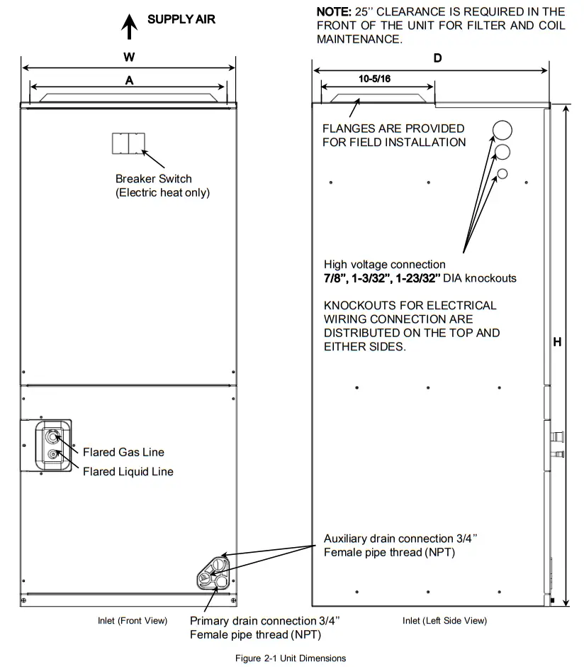
| Model Number | Dimensions (in.) | |||||
| H | W | D | A | Liquid Line Connection |
Gas Line Connection |
|
| 24 / 36 | 46-1/2 | 21 | 21 | 19-1/4 | 3/8 | 3/4 |
| 48 / 60 | 56 | 24-1/2 | 21 | 22-3/4 | 3/8 | 7/8 |
Select a solid and level site, keep enough space for proper installation and maintenance.
Adjust motor speed tap on indoor PCB to select correct air flow according to blower performance table.

Applications
3.1 Vertical up-flow and Horizontal right-flow
Vertical up-flow and horizontal right-flow configurations are the factory settings on all models.
If return air is to be ducted, install duct flush with floor. Use fireproof resilient gasket 1/8 to 1/4 in. thick between the ducts, unit and floor. Set unit on floor over opening.
IMPORTANT
Lightly tighten the drain connections so it won’t leak.
Using excessive force may cause damage to the drain connections. Torque applied to drain connections should not exceed 10.ft.lbs.

3.2 Evaporator coil

CAUTION
Horizontal units must be configured for right hand air supply.
Horizontal drain pan must be located under indoor coil. Failure to use the drain pan can result in property damage.
3.3 Installation in an unconditioned space
There are two pairs of coil rails in the air handler for default and counter flow application. If the air handler is installed in an unconditioned space, the two unused coil rails should be removed to minimize air handler surface sweating. The coil rails can be easily removed by taking off the 6 mounting screws from both sides of the cabinet.
Electrical Wiring
Field wiring must comply with the National Electric Code (C.E.C. in Canada) and any applicable local ordinance.
WARNING
Disconnect all power to unit before installing or servicing. More than one disconnect switch may be required to de-energize the equipment. Hazardous voltage can cause severe personal injury or death.
4.1 Power Wiring
It is important that proper electrical power is available for connection to the unit model being installed. Refer to the unit nameplate, wiring diagram and electrical data in the installation instructions.
- If required, install a branch circuit disconnect of adequate size, located within sight of, and readily accessible to the unit.
- A GFCI protection should be built in power before the unit. All installation and wiring shall meet the latest NEC requirements.
- When the electric heat is installed, units may be equipped with one or two 30~60 amp. circuit breakers.
These breakers protect the internal wiring in the event of a short circuit and serve as a disconnect. Circuit breakers installed within the unit do not provide over-current protection of the supply wiring and therefore may be sized larger than the branch circuit protection. - Supply circuit power wiring must be 167 ℉ minimum copper conductors only. Refer to electrical data in this section for ampacity, wire size and circuit protector requirements. Supply circuit protective devices may be either fuses or “HACR” type circuit breakers.
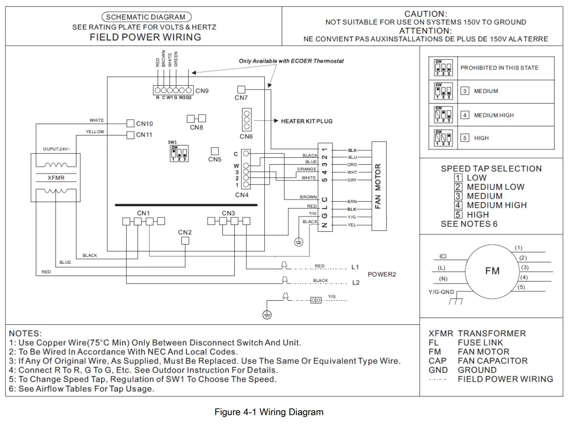
4.2 Control Wiring
Class 2 low voltage control wiring should not be run in conduit with main power wiring and must be separated from power wiring, unless class 1 wire of proper voltage rating is used.
- Low voltage control wiring should be color-coded 18 AWG. For lengths longer than 150 ft., 16 AWG. wire shall be used and maximum 225 ft..
- Refer to wiring diagrams attached to indoor and outdoor sections to be connected.
- Make sure separation of control wiring and power wiring has been maintained.
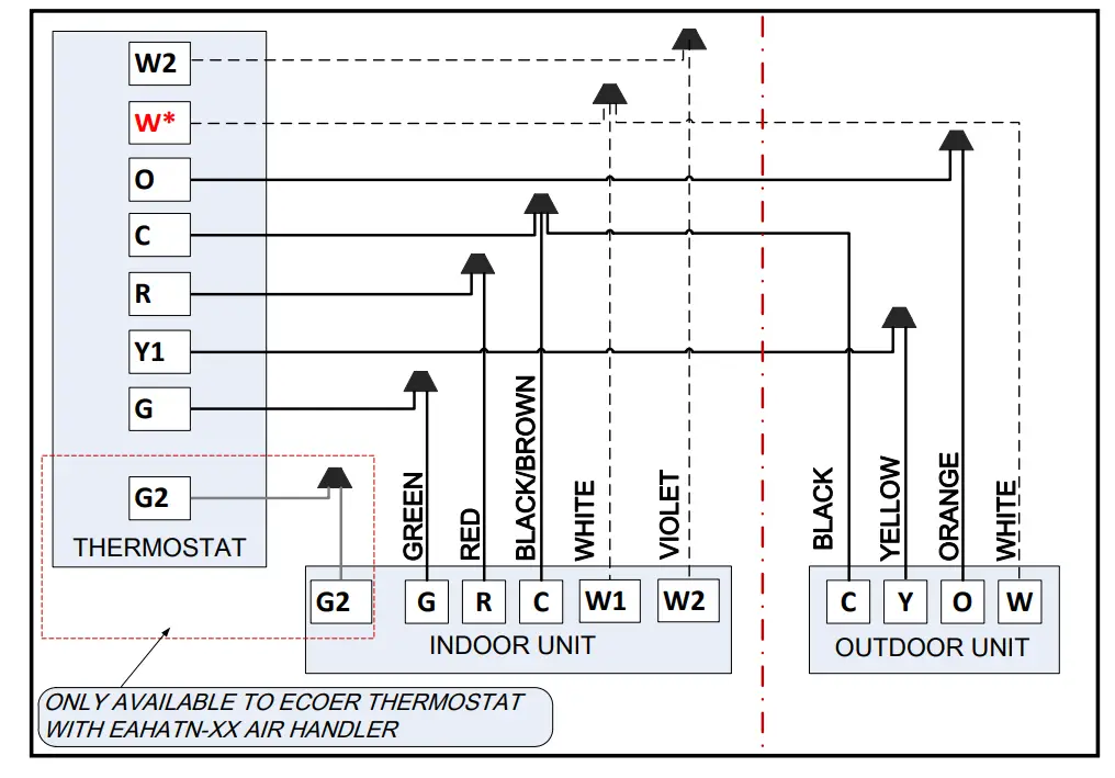
NOTES:
- Be sure power supply agrees with equipment nameplate.
- Power wiring and grounding of equipment must comply with local codes.
- Low voltage wiring to be No. 18 AWG minimum conductor.
- “-” means the electric auxiliary heat connection.
* Some thermostats may use W2/AUX for heat pump.
Figure 4-2 Schematic diagram for control wiring connection
Ecoer thermostat (EST01) has a default system type 10 designed for Ecoer heat pump to match with most traditional indoor air handlers or furnaces. To get two-stage fan control for E series air handlers, system type must be chosen to Type 9, 11, 12 and 13 accordingly.
Follow below steps to set SYSTEM TYPE
a) Press Menu at EST01 homepage, the screen will display DATE TIME, then press Next until you see
FACTORY SET.
b) Press Edit, the screen will display SYSTEM TYPE
c) Press + or – to set, then press Done to save the setting for system type.
System Types List
| Type | Descriptions | Application | Required Terminals |
| 0 | Cool only | ESI (AC only) + Air Handler | C, RC, Y1, G |
| 3 | Cool only | ESI + Air Handler | C, RC, Y1, 0, G |
| 6 | 1H/1C | ESI + Air Handler | C, RH, Y1, 0, G, W2* |
| 8 | 1H/1C | ESI + Air Handler | See details on EST Install and User Guide |
| 9 | 2H/2C (G/G2) | ESI + E series Air Handler | |
| 10 (Default) |
2H/1C | ESI + Air Handler ESI + Gas Furnace | |
| 11 | 2H/2C (G/G2) | ESI + E series Air Handler | |
| 12 | Cool only (G/G2) | AC only + E series Air Handler | |
| 13 | Cool only (G/G2) + W2 |
ESI- Ecoer Smart Inverter condensing unit * means optional connection
REMARKS:
For EST01 built on and prior to Dec 31, 2020, there is no output at O terminal if select Type 8 ~ 13. So type 6 can be used as a BACKUP for heat pump (Normal O signal output) application without two-stage fan control in cooling.
G2 signal occupies Tap (1) that requires powered terminal. According to the design, other brand 2-stage thermostats may use the following wiring diagrams to activate 2-stage fan control.
Other Brand 2-Stage Thermostat
3H/2C: Ecoer variable speed heat pump matches with EAHATN-XX.

* Refer to thermostat install guide for auxiliary heat connection. Some thermostats may use W2/AUX for heat pump.
4.3 Grounding
WARNING
The unit must be permanently grounded.
Failure to do so can result in electrical shock causing personal injury or death.
- Grounding may be accomplished by grounding metal conduit when installed in accordance with electrical codes to the unit cabinet. Grounding may also be accomplished by attaching ground wire(s) to ground lug(s) provided in the unit wiring compartment.
- Use of multiple supply circuits require grounding of each circuit to lug(s) provided in the unit.
4.4 Electrical Data
| Model Number |
Voltage-Phase-Hz | Power Supply Wiring Gauge |
Motor HP | Motor Steps |
Minimum Circuit AMPS. |
Fuse (A) |
| 24 | 208/230-1Ph-60Hz | 14 | 1/3 | 5 | 3.0 | 15 |
| 36 | 1/2 | 5. | ||||
| 48 | 3/4 | 8. | ||||
| 60 | 3/4 | 8. |
4.5 Electric Heat Data
| Kit Model | Model Number |
Electric Heat (kW) |
MIN. Circuit Ampacity |
MAX. Fuse or Breaker (HACR) Ampacity |
Fan speed | ||||||
| 240 | 208 | 240 | 208 | 1 | 2 | 3 | 4 | 5 | |||
| EHK05 | 24 | 5 | 25 | 22 | 30 | 25 | x | • | • | • | • |
| EHK10 | 10 | 49 | 43 | 60 | 50 | x | x | • | • | • | |
| EHK05 | 36 | 5 | 25 | 22 | 30 | 25 | x | • | • | • | • |
| EHK10 | 10 | 49 | 43 | 60 | 50 | x | x | • | • | • | |
| EHK15 | 5+10 | 25+49 | 22+43 | 30+60 | 25+50 | x | x | • | • | • | |
| EHK05 | 48 | 5 | 25 | 22 | 30 | 25 | x | • | • | • | • |
| EHK10 | 10 | 49 | 43 | 60 | 50 | x | • | • | • | • | |
| EHK15 | 5+10 | 25+49 | 22+43 | 30+60 | 25+50 | x | x | • | • | • | |
| EHK20 | 10+10 | 49+49 | 43+43 | 60+60 | 50+50 | x | x | x | • | • | |
| EHK05 | 60 | 5 | 25 | 22 | 30 | 25 | x | • | • | • | • |
| EHK10 | 10 | 49 | 43 | 60 | 50 | x | • | • | • | • | |
| EHK15 | 5+10 | 25+49 | 22+43 | 30+60 | 25+50 | x | x | • | • | • | |
| EHK20 | 10+10 | 49+49 | 43+43 | 60+60 | 50+50 | x | x | x | • | • | |
Electric heat kits are suitable for air handler multiple position installation. ● means available ×means unavailable
Safety Cautions All electric work must be performed by qualified personnel.
EHK series is designed and approved to be installed in the EAHATN series air handlers.
- Check the EHK label to confirm EHK size based on room load under lowest temperature ambient.
- Inspect all porcelain in insulators for breakage and the intact of heater element wire. Contact local distributor immediately if there is any occurred damage.
Warning - Disconnect all external power supplies before performing installation and servicing. Turn off accessory heater power switch if applicable. Failure to do so may cause serious injury.
- EHK must be properly grounded and use copper supply wires.
- Make sure to follow national electric code and local regulations.
- When installing it in an enclosed area such as a garage, heater elements should have a minimum clearance of 18’’ from the floor to insure the proper ventilation.
4.6 Electric Heat Installation Guide
STEP 1. Unfasten 4 screws to take away the blower access panel of the air handler.

STEP 2. Remove cover plate based on actual requirement.

STEP 3. Slide the kit into the duct and fasten the element (e.g. attachment and wires).
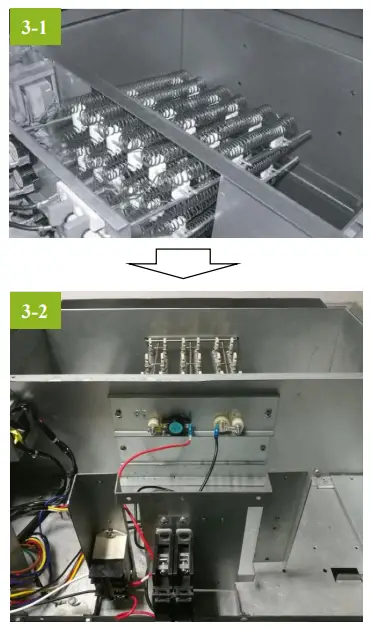
STEP 4. Install the circuit breaker into the mounting rail. Knock off the reserved cover forbreaker in blower access panel prior to put it back to the unit.

WARNING
Disconnect all power to unit before installing or servicing. More than one disconnect switch may be required to de-energize the equipment. Hazardous voltage can cause severe personal injury or death.

Airflow Performance
Airflow performance data is based on cooling performance with a coil and no filter in place. Check the Performance table for appropriate unit size selection. External static pressure should stay within the minimum and maximum limits shown in the table below in order to ensure proper airflow.
| Model Number | Motor Speed |
CFM (Watts) | ||||||||||
| External Static Presstre-Inches W.C.[KPa] | ||||||||||||
| 0 [0] | 0.1
(.02] |
0.16 (.04] |
0.2 [.05] |
0.3 [.07] |
0.4 (.10] |
0.5 (.12] |
0.6 (.15) |
0.7 (.17] |
0.8 (.20] |
|||
| SCFM | 1062 | 1031 | 998 | 981 | 947 | 901 | 869 | 823 | 789 | 742 | ||
| Tap (5) | Watts | 184 | 195 | 201 | 203 | 213 | 222 | 228 | 238 | 242 | 252 | |
| SCFM | 959 | 921 | 890 | 873 | 836 | 786 | 751 | 706 | 677 | 622 | ||
| Tap (4) | Watts | 138 | 145 | 152 | 156 | 162 | 171 | 178 | 188 | 196 | 204 | |
| 24 | Tap (3)- | SCFM | 855 | 825 | 790 | 769 | 733 | 679 | 646 | 595 | 560 | 494 |
| factory | Watts | 101 | 111 | 118 | 120 | 126 | 134 | 141 | 151 | 156 | 166 | |
| SCFM | 777 | 750 | 712 | 692 | 656 | 599 | 566 | 498 | 466 | 412 | ||
| Tap (2) | Watts | 80 | 89 | 96 | 98 | 104 | 113 | 119 | 127 | 135 | 145 | |
| SCFM | 694 | 663 | 620 | 599 | 562 | 499 | 455 | 390 | ||||
| Tap (1) | Watts | 60 | 68 | 74 | 76 | 82 | 89 | 95 | 104 | — | — | |
| 36 | Tap (5) | SCFM | 1455 | 1409 | 1374 | 1355 | 1320 | 1266 | 1229 | 1173 | 1126 | 956 |
| Watts | 293 | 300 | 306 | 309 | 316 | 326 | 331 | 338 | 346 | 370 | ||
| Tap (4) | SCFM | 1350 | 1302 | 1264 | 1242 | 1206 | 1145 | 1104 | 1038 | 897 | 824 | |
| Watts | 238 | 243 | 254 | 257 | 260 | 271 | 277 | 286 | 303 | 308 | ||
| Tap (3). factory |
SCFM | 1328 | 1281 | 1234 | 1215 | 1179 | 1118 | 1073 | 1007 | 862 | 798 | |
| Watts | 226 | 232 | 239 | 242 | 250 | 259 | 264 | 278 | 292 | 298 | ||
| Tap (2) | SCFM | 1235 | 1171 | 1130 | 1108 | 1062 | 1002 | 955 | 824 | 752 | 713 | |
| Watts | 185 | 189 | 196 | 199 | 205 | 214 | 221 | 238 | 245 | 248 | ||
| Tap (1) | SCFM | 1146 | 1091 | 1044 | 1022 | 982 | 908 | 823 | 748 | 708 | ||
| Watts | 150 | 156 | 163 | 167 | 174 | 184 | 196 | 202 | 207 | — | ||
| 48 | Tap (5) | SCFM | 2144 | 2106 | 2072 | 2052 | 2015 | 1962 | 1924 | 1864 | 1823 | 1768 |
| Watts | 627 | 632 | 639 | 643 | 649 | 661 | 670 | 681 | 684 | 696 | ||
| Tap (4) | SCFM | 1999 | 1966 | 1933 | 1915 | 1875 | 1819 | 1775 | 1713 | 1672 | 1582 | |
| Watts | 510 | 520 | 529 | 536 | 540 | 551 | 555 | 567 | 571 | 588 | ||
| Tap (3)- factory |
SCFM | 1788 | 1746 | 1714 | 1695 | 1660 | 1606 | 1565 | 1499 | 1452 | 1355 | |
| Watts | 367 | 374 | 389 | 393 | 404 | 422 | 429 | 440 | 449 | 458 | ||
| Tap (2) | SCFM | 1633 | 1596 | 1564 | 1554 | 1514 | 1467 | 1424 | 1342 | 1290 | 1231 | |
| Watts | 292 | 300 | 311 | 318 | 329 | 343 | 354 | 376 | 382 | 391 | ||
| Tap (1) | SCFM | 1504 | 1468 | 1428 | 1408 | 1362 | 1298 | 1244 | 1182 | 1160 | 1081 | |
| Watts | 228 | 242 | 250 | 255 | 264 | 279 | 291 | 309 | 318 | 327 | ||
| 60 | Tap (5) | SCFM | 2144 | 2106 | 2072 | 2052 | 2015 | 1962 | 1924 | 1864 | 1823 | 1768 |
| Watts | 627 | 632 | 639 | 643 | 649 | 661 | 670 | 681 | 684 | 696 | ||
| Tap (4) | SCFM | 1999 | 1966 | 1933 | 1915 | 1875 | 1819 | 1775 | 1713 | 1672 | 1582 | |
| Watts | 510 | 520 | 529 | 536 | 540 | 551 | 555 | 567 | 571 | 588 | ||
| Tap (3)- factory |
SCFM | 1788 | 1746 | 1714 | 1695 | 1660 | 1606 | 1565 | 1499 | 1452 | 1355 | |
| Watts | 367 | 374 | 389 | 393 | 404 | 422 | 429 | 440 | 449 | 458 | ||
| Tap (2) | SCFM | 1633 | 1596 | 1564 | 1554 | 1514 | 1467 | 1424 | 1342 | 1290 | 1231 | |
| Watts | 292 | 300 | 311 | 318 | 329 | 343 | 354 | 376 | 382 | 391 | ||
| Tap (1) | SCFM | 1504 | 1468 | 1428 | 1408 | 1362 | 1298 | 1244 | 1182 | 1160 | 1081 | |
| Watts | 228 | 242 | 250 | 255 | 264 | 279 | 291 | 309 | 318 | 327 | ||
Shaded boxes represent airflow outside the required 300-450cfm/ton.
NOTES:
Airflow based upon cooling performance at 230V with no electric heat and no filter. Airflow at 208V is approximately the same as 230V because the multi-tap ECM motor is a constant torque motor. The torque doesn’t drop off at the speeds in which the motor operates.
G2 signal occupies Tap (1) reserved for Ecoer thermostat to get even better dehumidification control in cooling.
This air handler keeps the selected TAP all the way in heating mode, but switches between the selected TAP and the lowest TAP (1) controlled by G and G2 signal sending from Ecoer thermostat (EST01). G signal will be turned OFF if the difference between indoor temp. and desired one is less than 3°F.
Indoor motor has 90 seconds delay after G/G2 inputs are gone no matter it runs cooling or heating.

The air distribution system has the greatest effect on airflow. For this reason, the contractor should use only industry-recognized procedures to finish ductwork.
Heat pump systems require a specified airflow. Each ton of cooling requires between 300 and 450 cubic feet per minute (CFM). Duct design and construction should be carefully done. System performance can be lowered dramatically through bad planning or workmanship.
Air supply diffusers must be selected and located carefully. They must be sized and positioned to deliver treated air along the perimeter of the space. Return air grilles must be properly sized to carry air back to the blower as well. Failure to follow these may cause abnormal noise and drafts.
The installers should balance the air distribution system to ensure proper quiet airflow to all rooms in the home. This ensures a comfortable living space. An air velocity meter or airflow hood can give a reading of system CFM.
Ductwork
Field ductwork must comply with the National Fire Protection Association NFPA 90A, NFPA 90B and any applicable local ordinance.
WARNING
Do not, under any circumstances, connect return ductwork to any other heat producing device such as fireplace insert, stove, etc. Unauthorized use of such devices may result in fire, carbon monoxide poisoning, explosion, personal injury or property damage.
Sheet metal ductwork run in unconditioned spaces must be insulated and covered with a vapor barrier.
Fibrous ductwork may be used if constructed and installed in accordance with SMACNA Construction Standard on Fibrous Glass Ducts. Ductwork must comply with National Fire Protection Association as tested by U/L Standard 181 for Class I Air Ducts. Check local codes for requirements on ductwork and insulation.
- Duct system must be designed within the range of external static pressure the unit is designed to operate against. It is important that the system airflow be adequate. Make sure supply and return ductwork, grilles, special filters, accessories, etc. are accounted for in total flow resistance. Refer to the airflow performance table in this manual.
- Design the duct system in accordance with “ACCA” Manual “D” Design for Residential Winter and Summer Air Conditioning and Equipment Selection. Latest editions are available from: “ACCA” Air Conditioning Contractors of America, 1513 16th Street, N.W., Washington, D.C. 20036. If duct system incorporates flexible air duct, be sure that the pressure drop Information (straight length plus all turns) shown in “ACCA” Manual “D” is accounted for in system.
- Supply plenum is attached to the 3/4” duct flanges supplied with the unit. Attach flanges around the blower outlet.
- Secure the supply and return ductwork to the unit flanges, using proper fasteners for the type of duct used and tape the duct-to-unit joint as required to prevent air leaks.
IMPORTANT
If an elbow is included in the plenum close to the unit, it must not be smaller than the dimensions of the supply duct flange on the unit.
The front flange on the return duct connected to the blower casing must not be screwed into the area where the power wiring is located. Drills or sharp screw points can damage insulation on wires located inside unit.
Drain Connections
Keep the coil connections sealed until refrigerant connections are made. Refer to condensing unit installation instructions for details on pipe size and insulation.
- Coil is shipped with Nitrogen. Evacuate the system before charging with refrigerant.
- Make sure the refrigerant pipes layout do not block service access.
- Purge the refrigerant pipes and indoor coil with dry nitrogen while brazing.
- Use a wet rag or an approved heat paste to protect the TXV sensing bulb during the brazing process.
Condensate Drain Connection
- Use a thin layer of Teflon paste, silicone or Teflon tape when making drain fitting connections.
- Do not over tighten fittings resulting in splitting pipe connections on the drain pan.

- Make sure the drain pipes layout do not block service access. Minimum clearance of 24 inches is required for filter, coil or blower removal and service access.
- Ensure the unit is level or pitched slightly toward primary drain connection so that water will drain smoothly from the pan. All horizontal drain pipes must be pitched downward away from the unit a minimum of 1/8” per foot of line to ensure proper drainage.
- Do not reduce drain pipe size less than connection size provided on condensate drain pan.
- Do not connect condensate drain pipe to a closed or open sewer pipe.
- The drain pipe should be insulated where necessary to prevent sweating and damage due to condensate forming on the outside surface of the line.
- Make provisions for disconnecting and cleaning of the primary drain pipe if it become necessary. Install a 3inch trap in the primary drain pipe as close as possible to the unit. Make sure that the top of the trap is below connection to the drain pan to allow complete drainage of pan.
- Auxiliary drain pipe should be connected to a place where it will be noticeable. Homeowner should be warned that a problem exists if water begins running from the auxiliary drain pipe.
- Test condensate drain pan and drain pipe after installation is complete. Pour enough water into drain pan, make sure that the drain pan is draining completely, no leaks are found in drain pipe fittings, and no water is draining from the termination of the primary drain pipe.
Air Filter
Filter application and replacement are critical to airflow, which may affect the heating and cooling system performance. Reduced airflow can shorten the life of the system’s major components, such as motor, heat relays, evaporator coil or compressor. Units should be sized for a maximum of 300 feet/min. air velocity or what is recommended for the filter type installed.
Ensure the air flow is in the range of 300~450CFM if adding high efficiency filters or electronic air filtration systems. Note that the overall performance and efficiency of the unit will be reduced because of pressure drop by filters.
IMPORTANT
Do not double filter the return air duct.
Do not filter the supply air duct which will change the performance of the unit and reduce airflow .
WARNING
Do not operate the system without filters. A portion of the dust suspended in the air may temporarily lodge in the duct. Any circulated dust particles could be heated and charred by contact with the air handler elements.
This residue could soil ceilings, walls, drapes, carpets and other articles in the house. Soot damage may occur without filters in place when certain types of candles, oil lamps or standing pilots are burned.
Air Filter Clean/Replacement
- Remove bolts to take the filter cover away.
- Hold the edge of the air filter and extract it out .
- Clean the air filter or use a new one to replace.

NOTE: AIR FILTER IS NOT FACTORY INSTALLED.
| Model Number | Dimensions (in.) | |||||
| Filter Size *1 | W | D | H | A | B | |
| 24 / 36 | 18 x 20 | 19-3/4 | 21 | 1 | 16 | 13-7/8 |
| 48 / 60 | 22 x 20 | 23-1/4 | 21 | 1 | 16 | 15-1/4 |
NOTE:
- Refer to the label on filter cover to install the correct filter size.
TXV Adjustment
To keep the best Ecoer Smart Inverter (ESI) systems’ performance and reliability, be sure liquid line subcooling (SC) and compressor suction superheat (SH) meet our requirements.
 Target SC and SSH in cooling
 ![]()
- If the LED displays “–” in AUTO charge mode for more than 20 minutes, stop charging and use a wrench to clockwise the TXV to ensure SH is no less than 7℉.
- In case that the cooling performance is abnormal due to improper superheat (i.e. SH >20℉). Proceed as followings to complete the field adjustment.
- Activate AUTO charge mode from outdoor condensing unit to fix compressor speed (RPS) by press BS4 for 5 seconds on PCB. Run the system for 15 to 20 minutes and check refrigerant coefficient number from LED display or ESS Pro App, add refrigerant until you get 0.6.
- Open the front panel of the air handler unit, then use a wrench to counterclockwise the TXV until SH ≤ 20℉. This will make more refrigerant flow into indoor coil for better cooling performance.
NOTE: Maintain a minimum of 15 minutes’ operation after every refrigerant amount or TXV opening adjustment (the TXV adjustment should be done at ¼ turn each time), then check live SC and SSH on Ecoer Smart Service Pro App.

Remember:
Put back the panel after TXV adjusted.
Manufacturer reserves the right to change specifications or designs without notice.
June 2023
©2021 ECOER INC.
43671 Trade Center Place, Suite 100,
Dulles, VA 20166 USA
Tel: 703-348-2538
www.ecoer.com