ESAB Swarm A20 Auto Darkening Welding Helmet User Manual

 WARNING
Read and understand this entire Manual and your employer’s safety practices before installing, operating, or servicing the equipment. While the information contained in this Manual represents the Manufacturer’s best judgment, the Manufacturer assumes no liability for its use.
Manual Number: 0-new
Published by:
ESAB Group Inc.
2800 Airport Rd.
Denton, TX 76208
940-566-2000
Copyright 2022 by ESAB. All rights reserved.
Reproduction of this work, in whole or in part, without written permission of the publisher is prohibited. The publisher does not assume and hereby disclaims any liability to any party for any loss or damage caused by any error or omission in this Manual, whether such error results from negligence, accident, or any other cause.
Original Publication Date: 02-16-2022
Revision Date:
Revision Date:
 WARNING
Before use, read and understand the instruction manual and follow all labels, employer´s safety practices and Safety Data Sheets (SDS).
WARNINGOnly qualified personnel should install, operate, maintain, and repair this unit.

ARC RAYS – Can injure eyes and burn skin
The arc, like the sun, emits ultraviolet (UV) and other radiation and can injure skin and eyes. Hot metal can cause burns. Training in the proper use of the processes and equipment is essential to prevent accidents. Therefore:
- Wear a welding helmet fitted with a proper shade of filter to protect your face and eyes when welding or watching.
- Wear approved safety glasses with side shields under your helmet.
- Before welding, adjust the auto-darkening filter lens sensitivity to meet the application. Warn bystanders not to watch the arc and not to expose themselves to the rays of the electric-arc or hot metal.
- Wear protective clothing made from durable, flame-resistant material. A flameproof apron may also be desirable as protection against radiated heat and sparks.
- Protect other personnel from arc rays and hot sparks with a suitable non-flammable partition or curtains.
- Use goggles over safety glasses when chipping slag or grinding. Chipped slag may be hot and can fly far. Bystanders should also wear goggles over safety glasses.

NOISE – Excessive noise can damage hearing
Protect your ears. Wear approved ear protection if noise level is high.
Fumes and gases can cause discomfort or harm, particularly in confined spaces. Shielding gases can cause asphyxiation. Therefore:
- Keep your head out of the fumes. Do not breathe the fumes and gases.
- Always provide adequate ventilation in the work area by natural or mechanical means. Do not weld, cut or gouge on materials such as galvanized steel, stainless steel, copper, zinc, lead beryllium or cadmium unless positive mechanical ventilation is provided. Do not breathe fumes from these materials.
- Do not operate near degreasing and spraying operations. The heat or arc can react with chlorinated hydrocarbon vapors to form phosgene, a highly toxic gas and other irritant gases.
- If you develop momentary eye, nose or throat irritation while operating, this is an indication that ventilation is not adequate. Stop work and take necessary steps to improve ventilation in the work area. Do not continue to operate if physical discomfort persists.
- Refer to ANSI/ASC Standard Z49.1 for specific ventilation recommendations.
FIRES AND EXPLOSIONS
Heat from flames and arcs can start fires. Hot slag or sparks can also cause fires and explosions. Therefore:
- Protect yourself and others from flying sparks and hot metal.
- Remove all combustible materials well away from the work area or cover the materials with a protective non-flammable covering. Combustible materials include wood, cloth, sawdust, liquid and gas fuels, solvents, paints and coatings paper, etc.
- Hot sparks or hot metal can fall through cracks or crevices in floors or wall openings and cause a hidden smoldering fire or fires on the floor below. Make certain that such openings are protected from hot sparks and metal.
- Do not weld, cut or perform other hot work until the work piece has been completely cleaned so that there are no substances on the work piece which might produce flammable or toxic vapors. Do not do hot work on closed containers, they may explode.
- Have fire extinguishing equipment handy for instant use, such as a garden hose, water pail, sand bucket, or portable fire extinguisher. Be sure you are trained in its use.
- Do not use equipment beyond its ratings. For example, an overloaded welding cable can overheat and create a fire hazard.
- After completing operations, inspect the work area to make certain there are no hot sparks or hot metal which could cause a later fire. Use fire watchers when necessary.
CAUTION!
This product is solely intended for arc welding.
CAUTION!
ADDITIONAL SAFETY INFORMATION
For more information on safe practices for electric arc welding and cutting equipment, ask your supplier for a copy of “Precautions and Safe Practices for Arc Welding, Cutting and Gouging”, Form 52-529.
The following publications are recommended:
- ANSI/ASC Z49.1 – “S
- AWS C5.5 – “Recommended Practices for Gas Tungsten Arc Welding”
- AWS C5.6 – “Recommended Practices for Gas Metal Arc welding”
- AWS SP – “Safe practices” – Reprint, Welding Handbook
- ANSI/AWS F4.1 – “Recommended Safe Practices for Welding and Cutting of Containers
That Have Held Hazardous Substances”
- OSHA 29 CFR 1910 – “Safety and Health Standards”
- CSA W117.2 – “Code for safety in welding and cutting”
- NFPA Standard 51B, “Fire Prevention During Welding, Cutting, and Other Hot Work”
- CGA Standard P-1, “Precautions for Safe Handling of Compressed Gases”
- ANSI Z87.1- “Occupational and Educational Personal Eye and Face Protection Devices’

Dispose of electronic equipment at the recycling facility!
In observance of European Directive 2002/96/EC on Waste Electrical and Electronic Equipment and its implementation in accordance with national law, electrical and/or electronic equipment that has reached the end of its life must be disposed of at a recycling facility. As the person responsible for the equipment, it is your responsibility to obtain information on approved collection stations. For further information contact the nearest ESAB dealer.

California Proposition 5 Warning
WARNING!
Welding or cutting equipment produces fumes or gases which contain chemicals known in the State of California to cause birth defects and, in some cases, cancer. (California Health & safety Code Section 25249.5 et s eq.)
WARNING!
This product can expose you to chemicals including lead, which are known to the State of California to cause cancer and birth defects or other reproductive harm. Wash hands after use. For more information, go to www.P65Warnings.ca.gov.
ESAB has an assortment of welding accessories and personal protection equipment for purchase. For ordering information contact your local ESAB dealer or visit us on our website.
Contents
SPECIFICATIONS
| Viewing Area | 93×43mm |
| Cartridge Size | 110×90mm |
| Arc Sensor | 2 |
| UV/IR Protection | DIN 13 |
| Light State | 4 |
| Dark State | External, Variable shade, 9-13 |
| Sensitivity Control | Low — High, by infinitely dial knob |
| Switch Time | ≤0.1ms, from Light to Dark |
| Delay Control | 0.1-0.8S, by infinitely dial knob, from Dark to Light |
| Power Supply | Solar cell and replaceable 1×CR2032 lithium battery |
| TIG AMP Rating | DC≥10, AC≥10 |
| Operating Temperature | -5°C to +55°C |
| Storing Temperature | -20°C to +70°C |
| Grind Functions | Yes |
| Low voltage indication | Yes |
PARTS BREAKDOWN
Parts List – ADF
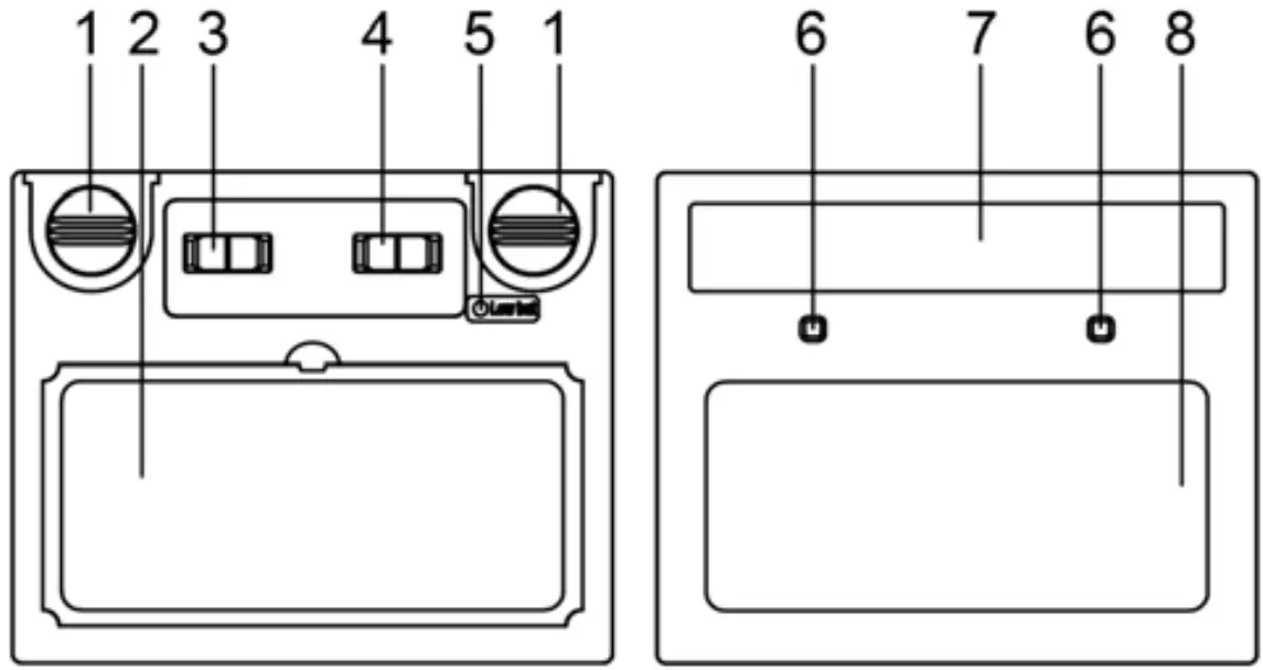
| Part # | Description |
| 1 | Shade control |
| 2 | Self-test Button |
| 3 | Low Voltage Indicator |
| 4 | Delay Control Knob |
| 5 | Sensitivity Control Knob |
| 6 | LCD |
| 7 | Lithium Battery |
| 8 | Arc Sensor |
| 9 | Solar Panel |
| 10 | UV/IR Filter |
Parts List
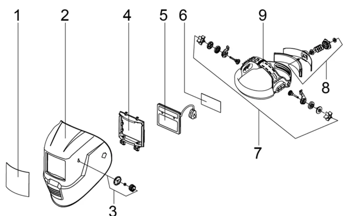
| Part # | Description |
| 1 | Front cover lens |
| 2 | Helmet shell |
| 3 | Shade control |
| 4 | ADF holder |
| 5 | ADF |
| 6 | Inside cover lens |
| 7 | Headband angle Adjusting Knob |
| 8 | Headband diameter Adjusting Knob |
| 9 | Headband Height Adjusting Pin |
OPERATION
- Remove the protective film from NEW exterior and interior protective lenses.
- Press the “TEST” button to ensure the battery is able to power the Auto-Darkening Filter (ADF).
- Inspect the ADF for damage or discoloration.
- Clean the outer and inner protective lenses and inspect for scratches or other damage. If scratches or other damage are evident, replace those parts before use.
- Inspect all parts of the helmet for signs of excessive wear or damage. Do not use if there is any signs of damage and replace those parts immediately.
- Ensure all moving parts and latches are tight and secure.
- Always choose the appropriate shade for the type of welding in which you are engaged.
| Welding Process | Arc Current (Amperes) | |||||||||||||||||||||||||||||||||||
| 1.5 | 6 | 10 | 15 | 30 | 40 | 60 | 70 | 100 | 125 | 150 | 175 | 200 | 225 | 250 | 300 350 | 400 | 450 | 500 | 600 | |||||||||||||||||
| SMAW | 8 | 9 | 10 | 11 | 12 13 | 14 | ||||||||||||||||||||||||||||||
| MAG | 8 | 9 | 10 | 11 | 12 | 13 | 14 | |||||||||||||||||||||||||||||
| TIG | 8 | 9 | 10 | 11 | 12 | 13 | ||||||||||||||||||||||||||||||
| MIG (heavy) | 9 | 10 | 11 | 12 | 13 | 14 | ||||||||||||||||||||||||||||||
| MIG (light) | 10 | 11 | 12 | 13 | 14 | |||||||||||||||||||||||||||||||
| PAC | 9 | 10 | 11 | 12 | 13 | |||||||||||||||||||||||||||||||
| PAW | 4 | 5 | 6 | 7 | 8 | 9 | 10 | 11 | 12 | |||||||||||||||||||||||||||
| Note |
|
|||||||||||||||||||||||||||||||||||


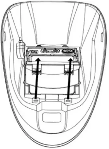
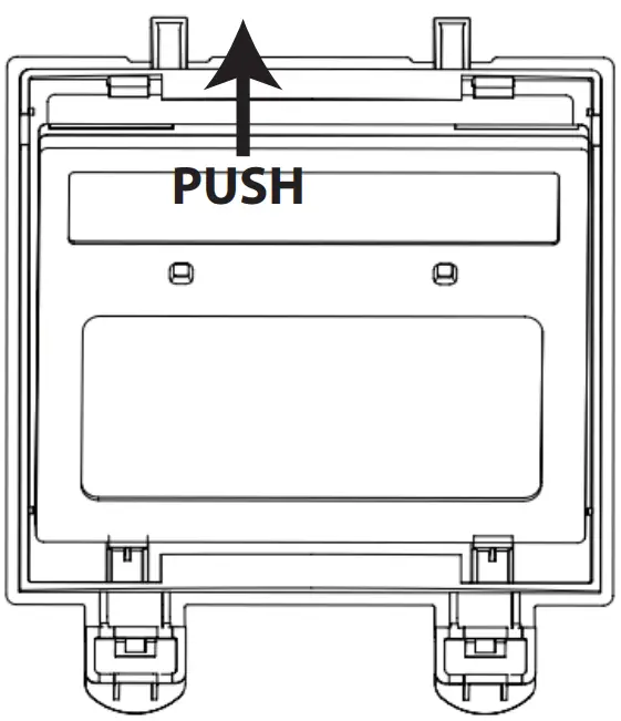
- Lift up one edge of the inner cover lens and pull the cover lens away from the filter
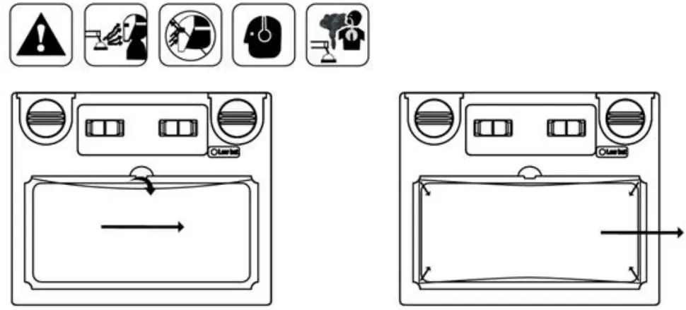
- Remove the protective film on the new inner lens cover, feed one side of the lens cover

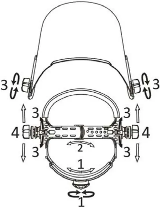
- Adjust the headgear diameter with the ratcheting twist knob on the back. Push the knob in to unlock the mechanism and twist clockwise to tighten and counterclockwise to loosen.
- The height of the headgear can be adjusted by using the inlock strap (2). Simply push the pin out, slide the strap into position and push the pin into the nearest pin hole location.
- To adjust the viewing angle, loosen the knob (3) on both sides of the helmet and change angle locking mechanism to the desired tilt position. There are 5 available positions, with helmet set to the middle position by default. Once the desired angle adjustment is set, tighten the knobs until snug. The helmet should still swing up, but it should not drift downward when in place for welding.
- To adjust the distance between the user’s face and ADF, loosen the knobs (3) on both sides of the helmet until the headband can move back and forth freely, reposition the headband (4) at one of the 3 slots as desired (The headband is positioned in the middle by default). This should be done one side at a time and both sides should be located at the same position for proper auto-darkening filter operation.
MAINTENANCE
- Please use tissues, lens wiping paper or clean cotton cloth and detergent to clean filter.
- Please use neutral detergent to clean out shell of weld cap and sweatband.
- Please replace outside and inside protector and sweatband regularly.
- Please do not use corrosive solvent or gasoline to dilute detergent.
- Instructions for cleaning and disinfection: Clean the welding filter with a clean lint free tissue or cloth, Do not immerse the helmet into water. Do not use solvents
Keep the sensors, solar cell and filter lens clean. Clean filter cartridge and helmet shell by using a soapy water solution and soft cloth. Do not use solvents or abrasive cleaning detergent. Switch the product to Grind Mode and put it in a clean, dry location for storage.
TROUBLE SHOOTING
| PROBLEM(S) | POSSIBLE CAUSE(S) | SUGGESTED SOLUTION(S) |
| Difficult to see through the auto- darkening filter (ADF) | The protective film is on the front or inside cover lens | Remove protective film |
| The front or inside protective cover lens is dirty or damaged | Clean or replace front/inside cover lens | |
| The ADF is dirty | Clean filter lens | |
| The ADF does not darken when arc is struck | Sensors or Solar Panel are blocked | Make sure sensors or solar panel are exposed to weld arc without blocking |
| Sensitivity is set to LOW | Adjust sensitivity to required level | |
| The ADF darkens without arc | Sensitivity is set to HIGH | Adjust sensitivity to required level |
| The ADF remains dark after welding | Delay is set to MAX | Adjust delay to required level |
MARKINGS
- Markings on the ADF
3/11 GX 1/1/1/2/379
Definition: 3=light state, 11= dark state, GX=manufacturer identification, 1=optical
class, 1=diffusion of light class, 1=Variation in Luminous transmittance class, 2=angle
dependence class, all according to the EN379 testing standard
GX Z87 W3/11
Definition: GX=manufacturer identification, Z87 refers to the ANSI testing standard,
W3/11=light state/dark states
GX Z94.3 W3/11
Definition: GX=manufacturer identification, Z94.3 refers to the CSA testing standard,
W3/11=light state/dark states - Markings on the helmet shell
GX EN175 F
Definition: GX=manufacturer identification, EN175
testing standard, F=resistance against low energy impact 45 m/s
Definition: GX=manufacturer identification, Z87 refers to the ANSI testing standard
Definition: GX=manufacturer identification, Z94.3 refers to the CSA testing standard
- Markings on the Front cover lens
GX 1 B
Definition: GX=manufacturer identification, 1=optical class,
B=resistance against energy impact 120m/s according to the EN166 testing standard. - Marking on the Inner cover lens
GX 1 F
Explanation GX=manufacturer identification, 1=optical class,
F=resistance against low energy impact 45m/s according to the EN166 testing standard. NOTICE REGARDING MARKINGS: If the symbols of the marking are not common to different parts of the protection equipment, the lower protection level shall be assigned to the complete protection equipment.
WARNING!Materials which may come into contact with the wearer’s skin could cause allergic reactions to some individuals
WARNING!Safety eye wear must be worn to protect against high speed particles. Approved, impact-resistant over-the-glass safety eye wear must be worn over standard ophthalmic spectacles to protect against impacts.
WARNING!If protection against high speed particles at extremes of temperature is required then the selected safety eye wear should be marked with the letter T immediately after the impact letter, i.e. FT, BT or AT. If the impact letter is not followed by the letter T then the eye protector shall only be used against high speed particles at room temperature. This isn (is not) accordance to EN166 testing standards.
The described PPE satisfies the requirements of European Directives 2001/95/EC and will continue to comply with the requirements of (EU) Regulation 2016/425 from 21/04/2018,
CSA Z94.3-2020
EN 379:2003+A1:2009
EN175:1997-08
EN166:2001
