Contents
ABB MO165 Motor Starter
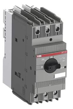
Product Information
- Product Model: MO165 / MO165-B
- Manufacturer: ABB STOTZ-KONTAKT GmbH
- Address: Eppelheimer Str. 82, 69123 Heidelberg, Germany
- Website: https://www.abb.com/lowvoltage
- Product Manual: Download
Product Usage Instructions
- Warning: Hazardous voltage! Refer to operating instructions.
- Disconnect and lock out power before working on this device.
- Installation should only be performed by persons with electrotechnical expertise.
- Refer to the English text in case of doubt.
Note: For detailed installation instructions and safety precautions, please refer to the product manual.
Installation instructions
Warning: Hazardous voltage!
Refer to operating instructions. Disconnect and lock out power before working on this device.
Attention! Installation by a person with electrotechnical expertise only. The English text applies in case of doubt.
INSTALLATION INSTRUCTION


WARNING
When an overload or a fault current interruption occurs, circuits must be checked to determine the cause of the interruption. When a fault condition exists, the current-carrying components should be examined and replaced when damaged, and the integral current sensors must be replaced to reduce the risk of fire or electric shock. To maintain overcurrent, short-circuit, and ground-fault protection, the manufacturer’s instructions for selection of overload and short-circuit protection must be followed to reduce the risk of fire or electric shock. Suitable for installation in an enclosure with minimum dimemsions of 290 x 130 x 190 mm
When used with PS2-xx-125 busbars, suitable for installation in an enclosure with minimum dimensions:
| Type | Height (mm) | Width (mm) | Depth (mm) |
| PS2-2-0-125 | 280 | 165 | 195 |
| PS2-3-0-125 | 280 | 248 | 195 |
| PS2-4-0-125 | 280 | 330 | 195 |
| PS2-2-2-125 | 280 | 219 | 195 |
| PS2-3-2-125 | 280 | 329 | 195 |
| PS2-4-2-125 | 280 | 438 | 195 |
Combination motor controller Type F, when used with AF contactor series and overload relays EF or TF series and optional connector BEAxx”
| Combination Motor Controller Type F
Type 1 Coordination |
||||||
| Type | 480Y/277V
[kA] |
OL Relay | Contactor | 600Y/347V
[kA] |
OL Relay | Contactor |
| MO165-16 | 65 | EF19-18.9 | AF09…AF38 | 50 | EF19-18.9 | AF09…AF38 |
| MO165-20 | 65 | EF45-30 | AF26…AF38 | 50 | EF45-30 | AF26…AF38 |
| MO165-25 | 65 | EF45-30 | AF26…AF38 | 50 | EF45-30 | AF26…AF38 |
| MO165-32 | 65 | EF45-45 | AF26…AF38 | 50 | EF45-45 | AF26…AF38 |
| MO165-42 | 65 | EF65 | AF40…AF65 | 30 | EF65 | AF40…AF65 |
| MO165-54 | 65 | EF65 | AF40…AF65 | 30 | EF65 | AF40…AF65 |
| MO165-65 | 65 | EF65 | AF40…AF65 | 30 | EF65 | AF40…AF65 |
| MO165-73 | 50 | EF96 | AF80…AF96 | – | – | – |
| MO165-80 | 50 | EF96 | AF80…AF96 | – | – | – |
| Combination Motor Controller Type F
Type 1 Coordination |
||||||
| Type | 480Y/277V
[kA] |
OL Relay | Contactor | 600Y/347V
[kA] |
OL Relay | Contactor |
| MO165-16 | 65 | TF42 | AF09…AF38 | 30 | TF42 | AF09…AF38 |
| MO165-20 | 65 | TF42 | AF26…AF38 | 30 | TF42 | AF09…AF38 |
| MO165-25 | 65 | TF42 | AF26…AF38 | 50 | TF42 | AF26…AF38 |
| MO165-32 | 65 | TF42 | AF26…AF38 | 50 | TF42 | AF26…AF38 |
| MO165-42 | 65 | TF65 | AF40…AF65 | 30 | TF65 | AF40…AF65 |
| MO165-54 | 65 | TF65 | AF40…AF65 | 30 | TF65 | AF40…AF65 |
| MO165-65 | 65 | TF65 | AF40…AF65 | 30 | TF65 | AF40…AF65 |
| MO165-73 | 50 | TF96 | AF80…AF96 | – | – | – |
| MO165-80 | 50 | TF96 | AF80…AF96 | – | – | – |
| Combination Motor Controller Type F
Type 2 Coordination |
||||||
| Type | 480Y/277V
[kA] |
OL Relay | Contactor | 600Y/347V
[kA] |
OL Relay | Contactor |
| MO165-73 | 50 | EF96 | AF80…AF96 | – | – | – |
| MO165-80 | 50 | EF96 | AF80…AF96 | – | – | – |
| Combination Motor Controller Type F
Type 2 Coordination |
||||||
| Type | 480Y/277V
[kA] |
OL Relay | Contactor | 600Y/347V
[kA] |
OL Relay | Contactor |
| MO165-73 | 50 | TF96 | AF80…AF96 | – | – | – |
| MO165-80 | 50 | TF96 | AF80…AF96 | – | – | – |
- ABB STOTZ-KONTAKT GmbH
- Eppelheimer Str. 82
- 69123 Heidelberg
- Germany
- https://www.abb.com/lowvoltage