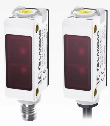
LANBAO PSE-YC Series Optical Sensor
Contents
Precautions
- Please make sure that the power supply voltage is within the rated value before powering on.
- The time from powering-on to normal detection of the sensor is 100 ms, please ensure that the sensor is used after 100 ms of powering on.
- When using different power sources for the sensor and load, be sure to turn on the power of the sensor first .
- When the sensor is not used, it is recommended to cut off the power of the load first and then turn off the power of the sensor .
- Do not subject the sensor to severe external forces (such as hammer hits, etc.) during installation, so as not to damage the sensor performance .
- Avoid using thinner, alcohol or other organic solvents when cleaning.
Safety Warning
- Do not use in an environment with flammable, explosive or corrosive gases.
- Do not use in oil or chemical environments.
- Do not use in a high humidity environment.
- Do not use in direct sunlight.
- Do not use in other environmental conditions that exceed the rated value.
- Do not disassemble, repair or modify this product without authorization.
Scrap Treatment
- When the product is scrapped, please dispose of it as industrial waste.
Distance Adjustment
- Turn the sensitivity adjuster fully.
BGS function: CounterclockwiseFGS function: Clockwise
- BGS function: In the object present condition, turn the sensitivity adjuster and confirm the point A where the sensor enters the sensing state. FGS function: In sensing back-ground condition, turn the sensitivity adjuster and confirm the point A where the sensor enters the non-sensing state.
- BGS function: After removing the sensing object, turn the sensitivity adjuster and confirm the point B where the sensor enters the non-sensing state. FGS function: In the object present condition, turn the sensitivity adjuster and confirm the point B where the sensor enters the sensing state.
(If the sensor does not enter the “Light” state operation even when the sensing adjuster is turned fully clockwise, the postion is point B.) - The optimum postion to stably detect objects is the center point between A and B.
Technical specifications
|
Detection type |
Background suppression | ||||||||
| NPN NO | NPN NC | PNP NO | PNP NC | NPN | PNP | NPN |
PNP |
||
|
Format |
Cable | PSE-YC5DNOR | PSE-YC5DNCR | PSE-YC5DPOR | PSE-YC5DPCR | PSE-YC25DNBR | PSE-YC25DPBR | PSE-YC35DNBR |
PSE-YC35DPBR |
|
Connector |
PSE-YC5DNOR-E3 | PSE-YC5DNCR-E3 | PSE-YC5DPOR-E3 | PSE-YC5DPCR-E3 | PSE-YC25DNBR-E3 | PSE-YC25DPBR-E3 | PSE-YC35DNBR-E3 |
PSE-YC35DPBR-E3 |
|
|
Sensing distance |
0,2…5cm | 0,5…25cm | 0,5…35cm | ||||||
| Return difference | < 2% |
< 10% |
|||||||
|
Distance adjustment |
5-turn knob adjustment | ||||||||
| Light source |
Red light(630nm) |
||||||||
|
Light spot size |
⌀ 2 mm (5 cm) | ⌀ 6 mm (25 cm) | |||||||
| Supply voltage |
10…30 V DC |
||||||||
|
Consumption current |
≤20mA | ||||||||
| Load current |
≤100mA |
||||||||
|
Voltage drop |
≤2V | ||||||||
| Circuit protection |
Short circuit, Reverse polarity, Overload, Zener protection |
||||||||
|
BGS/FGS Switch |
The white wire connected to the positive electrode or floating is BGS, and the white wire connected to the negative electrode is FGS |
/ |
|||||||
|
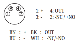
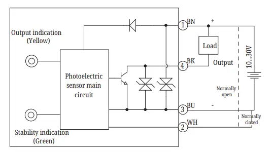
NO/NC Switch |
/ |
The white wire connected to the positive electrode or floating is NO, and the white wire connected to the negative electrode is NC |
|||||||
|
Response time |
≤0,5ms | ≤1ms | |||||||
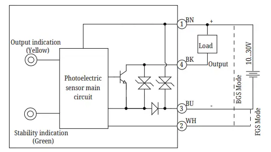
| Indicator |
Green: Power indicator; Yellow: Output, overload or short circuit |
||||||||
|
Anti-ambient light |
Sunlight interference ≤ 10,000 lux; Anti incandescent light interference ≤ 3,000 lux | ||||||||
| Ambient temperature |
-25℃…55℃ |
||||||||
|
Storage temperature |
-25℃…70℃ | ||||||||
| Protection degree |
IP67 |
||||||||
|
Certification |
CE | ||||||||
| Material |
PC+ABS |
||||||||
|
Lens |
PMMA | ||||||||
| Weight |
Cable: about 50g; Connector: about 10g |
||||||||
|
Accessories |
Screw ×2, Mounting bracket ZJP-8, Operation manual |
||||||||
Note: The standard detection target is a white card of 20cm*20cm(90% reflectivity)
Accessory Dimensions(Sold Separately)
The following accessories need to be ordered additionally except for the ZJP-8 type mounting bracket.
M8 Connector: CS S48L-3-2
M8 Connector: CS S49L-3-2
Mounting Bracket: ZJP-8 (accessory)
Dimensions
Background Suppression-Connector
Background Suppression-Cable
Terminal Wiring Diagram
PSE-YC5
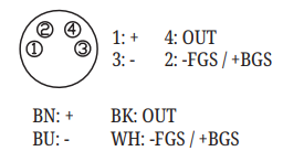
PSE-YC25, YC35
Wiring diagram
PSE-YC5(NPN Output)
PSE-YC5(PNP Output)
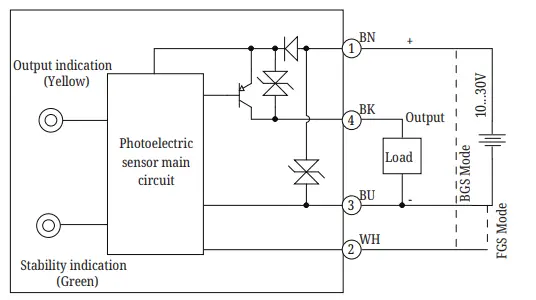
PSE-YC25, YC35(NPN Output)
PSE-YC25, YC35(PNP Output)

Mounting
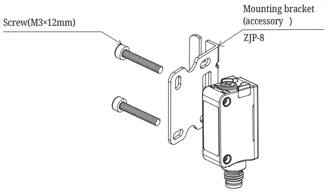
Note: When installing this product, please keep the tightening torque below 0,5 N·m.
CUDTOMER SUPPORT
eko-com.ru
Tel.: 8 (800) 333-70-75
E-mail: [email protected]
