![]() 51.2V Rack Mode
51.2V Rack Mode
Lithium Energy Storage Battery
USER INSTRUCTION
Contents
Product Description
This rack mode lifepo4 lithium battery belongs to one of the series of household energy storage products that are independently designed and developed. It has long cycle life, high safety standard BMS software protection and strong housing, exquisite looks, and easy installation, etc. It is widely used in energy storage system with offgrid inverters, on-off grid inverters and hybrid inverters. *This interface design is only for reference, it may change according to different demands
Product Function Description
2.1 Product Specifications
| Items | Condition | Specification | ||||
| Nominal Capacity | Standard charge/discharge | 50.0Ah | 100.0Ah | 150.0Ah | 200.0Ah | |
| Nominal Voltage | Average | 51.2V | 51.2V | 51.2V | 51.2V | |
| Standard Charging Refer to 3.1 | Constant current Constant voltage End current(Cut off) | 10A 56.8V 0.2A |
20A 56.8V 0.5A |
30A 56.8V 0.7A |
40A 56.8V 1A |
|
| Charging Voltage | / | 56.8V | 56.8V | 56.8V | 56.8V | |
| Max. Continuous Charge Current | 25±3℃ | 25.0A | 50.0A | 75.0A | 100.0A | |
| Standard Discharging Refer to 3.2 | Constant current End voltage(Cut off) | 25.0A 43.2V |
50.0A 43.2V |
75.0A 43.2V |
100.0A 43.2V |
|
| Max Continuous Discharge Current | 25±3℃ | 50.0A | 100.0A | 100.0A | 100.0A | |
| Max Output Power | 25±3℃ | 2.56KW | 5.12KW | 5.12KW | 5.12KW | |
| Operating Temperature | Charge | / | 0℃~ 60℃ | |||
| Discharge | / | -20℃~ 60℃ | ||||
| Storage Temperature | 1 month 3 month 6 month |
-20℃~ 45℃ -20℃~ 35℃ -20℃~ 25℃ |
||||
| Power Cable Terminal | / | Ring Terminal | ||||
2.2 Parallel Connection
When Connect the batteries in parallel, connect the positive terminal and positive terminal(red colour) in parallel, and the negative terminal and negative terminal (black colour) in parallel, the max parallel quantity is 15pcs, as shown in the figure
below: Solar System Structure
 2.3 Dial Code Switch Settings (parallel connection needed)
 When the battery packs are connected in parallel, the dial code switch of each battery can be used to distinguish different Pack addresses. The hardware address can be set through the dial code switch on the board. The definition of the dial code switch refer to the following table.
| ADD | Dial switch position | Explain | |||
| #1 | #2 | #3 | #4 | ||
| 0 | OFF | OFF | OFF | OFF | No parallel connection, only 1 pcs |
| 1 | ON | OFF | OFF | OFF | Pack1(master) |
| 2 | OFF | ON | OFF | OFF | Pack2 |
| 3 | ON | ON | OFF | OFF | Pack3 |
| 4 | OFF | OFF | ON | OFF | Pack4 |
| 5 | ON | ON | ON | OFF | Pack5 |
| 6 | OFF | ON | ON | OFF | Pack6 |
| 7 | ON | ON | ON | OFF | Pack7 |
| 8 | OFF | OFF | OFF | ON | Pack8 |
| 9 | ON | OFF | OFF | ON | Pack9 |
| 10 | OFF | ON | OFF | ON | Pack10 |
| 11 | ON | ON | OFF | ON | Pack11 |
| 12 | OFF | OFF | ON | ON | Pack12 |
| 13 | ON | OFF | ON | ON | Pack13 |
| 14 | OFF | ON | ON | ON | Pack14 |
| 15 | ON | ON | ON | ON | Pack15 |
2.4 Communication Function
a) RS232 communication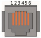
| RS232 Port use 6P6C vertical RJ11 Socket | |
| RJ11 Pin | Define |
| Pin 1、 2、6 | NC(empty) |
| Pin 3 | TX(computer receives data) |
| Pin 4 | RX(computer sends data) |
| Pin 5 | GND(ground) |
BMS can communicate with the upper computer through RS232 interface, so that it can monitor all kinds of battery information, including battery voltage, current and temperature, working status etc. The default baud rate is 9600bps.
b) RS485-1 / CAN main communication If you need to communicate with the monitoring device through RS485 or Can, the monitoring device will be used as the host, and the address setting range of other batteries will be 2~15 according to the polling data of the address.
The product adopts isolated communication design, supports RS485/CAN communication mode, RS485 communication default baud rate is 9600 bps, 8 bit data bit, 1 bit stop bit, no test bit; The default baud rate of CAN communication is 500Kbps;
| RS485 & CAN use 8P8C vertical RJ45 socket | |||
| RS485 PIN | Define | CAN PIN | Define |
| 1、8 | RS485-B1 | 9、10、11、14、16 | NC |
| 2、7 | RS485-A1 | 12 | CANL |
| 3、6 | GND | 13 | CANH |
| 4、5 | NC | 15 | GND |
c) RS485-2 communication for parallel connectionWith dual RS485 interfaces, the default baud rate is 9600bps. If you need to communicate the batteries in parallel with the monitoring device or inverter, you need to connect each battery with RS485-2 ports, so the host battery can read the information of each battery.
| RS485-A & RS485-B use 8P8C vertical RJ45 socket | |||
| RS485-A PIN | Define | RS485-B PIN | Define |
| 1、8 | RS485-B | 9、16 | RS485-B |
| 2、7 | RS485-A | 10、15 | RS485-A |
| 3、6 | GND | 11、14 | GND |
| 4、5 | NC | 12、13 | NC |
2.5 LED Indication Function
The current power consumption and operation status of the product are shown through LED indicator Light (See Table 1, Table 2, and Table 3 for details) Working status indication
| Status | Normal/ warning/ protection | ON/OFF | RUN | ALM | Battery capacity LED | Specification | |||||
| Power off | Dormancy | NO | NO | NO | NO | NO | NO | NO | NO | NO | All NO |
| Ready mode | Normal | YES | Flash1 | NO | Indicate according to the battery capacity | Ready mode status | |||||
| Warning | YES | Flash1 | Flash3 | Module low voltage | |||||||
| Charging | Normal | YES | YES | NO | Indicate according to the battery capacity(LED 2 flash when it indicate the highest battery capacity) | LED 2 flash when it is highest battery capacity, ALM do not flash when over- charging | |||||
| Warning | YES | YES | Flash3 | ||||||||
| Over charging protection | YES | YES | NO | YES | YES | YES | YES | YES | YES | If there is no mains power, the indicator turns to standby | |
| Temperatur e over current, failure protection | YES | NO | YES | NO | NO | NO | NO | NO | NO | Stop charging | |
| Dis charging | normal | YES | Flash3 | NO | Indicate according to the battery capacity | ||||||
| warning | YES | Flash3 | Flash3 | ||||||||
| Under voltage protection | YES | NO | NO | NO | NO | NO | NO | NO | NO | Stop discharging | |
| Over temperature, current, short circuit, reverse connection, failure protection | YES | NO | YES | NO | NO | NO | NO | NO | NO | Stop discharging | |
| Invalida tion | NO | NO | YES | NO | NO | NO | NO | NO | NO | Stop charging and discharging | |
Capacity Indicator
| Status | Charging | Discharging | |||||||||||
| Capacity dictator |
L6 |
L5 |
L4 |
L3 |
L2 |
L1 |
L6 |
L5 |
L4 |
L3 |
L2 |
L1 |
|
| Battery level (%) | 0~16.6% | NO | NO | NO | NO | NO | Flash2 | NO | NO | NO | NO | NO | YES |
| 16.6~33.2% | NO | NO | NO | NO | Flash 2 | YES | NO | NO | NO | NO | YES | YES | |
| 33.2~49.8% | NO | NO | NO | Flash 2 | YES | YES | NO | NO | NO | YES | YES | YES | |
| 49.8~66.4% | YES | YES | Flash2 | YES | YES | YES | NO | NO | YES | YES | YES | YES | |
| 66.4~83.0% | NO | Flash2 | YES | YES | YES | YES | NO | YES | YES | YES | YES | YES | |
| 83.0~100% | Flash 2 | YES | YES | YES | YES | YES | YES | YES | YES | YES | YES | YES | |
| Working dictator |
YES | Flash 3 | |||||||||||
LED Flashing Instructions
| Flash way | Bright | NO |
| Flash 1 | 0.25S | 3.75S |
| Flash 2 | 0.5S | 0.5S |
| Flash 3 | 0.5S | 1.5S |
Note:
The LED indicator alarm can be enabled or disabled through the host computer.
The factory default is enabled.
2.6 Sleep Mode
Without RS485/CAN communication, charging/discharging or pressing any buttons, 24h later this power box will enter into sleep mode to save the power, it has small self-consumption;
2.7 Awake Mode
When the system is in sleep mode, if any of the following requirements, the system will quit the sleep mode and enter into the normal operation mode.
- Automatic wake-up after charged with voltage higher than 48V;
- Press the key button for 3~6 second, release the key button and activate it;
- Access communication line (RS232), activate it with upper computer software.
2.8Power-off mode wake-up
- Charging voltage should be greater than 52.5V.
- Press the button for longer than 2 seconds and release the button.
2.9This product is designed with the function of compoundbutton.
In the normal operation process, long press this button once (>6s), then release the button and the product will be reset and restarted;
Electrical Specification
(Unless there is special requirement, the test shall be done under temperature of 25±2℃ and with relative humidity of 45~85%.)
| Items | Test Condition | Standard | ||||
| 3.1 Standard Charge | The standard charge means charge the battery in temperature below 25±3℃with initial charge current of 10A(50Ah)/ 20A(100Ah)/ 30A(150Ah)/ 40A(200Ah) and with constant voltage of 56.8V, then charge with constant voltage of 56.8V and with floating current taper to 0.2A(50Ah)/ 0.5A(100Ah)/ 0.7A(150Ah)/ 1A(200Ah) cut-off (Charger should be exclusively designed for lithium battery, with an accuracy of ±0.05V) within 6 hours. | / | ||||
| 3.2 Standard Discharge | After battery is charged fully in accordance with the standard and then discharge to voltage 43.2V with discharge current of 10A(50Ah)/ 20A(100Ah)/ 30A(150Ah)/ 40A(200Ah). The minimum gap time between charge and discharge period is 30 minutes. | Minimum Capacity ≥50/100/150/ 200Ah | ||||
|
3.3 Cycle Life |
After the completion of standard charge and 30 minutes’ rest, discharge with 80% DOD with constant current of 0.2C in the (25±3℃) environment, after 3000 cycles, rest it for 1 day and test the capacity in accordance with the above 3.2 | Capacity≥80% Minimum Capacity | ||||
| 3.4 Discharge Character | Discharge current | Discharge Temperature | At -10℃: Discharge Capacity≥50% At 0℃: Discharge capacity ≥ 80% At 25℃ Discharge capacity ≥ 100% At 40℃ Discharge capacity ≥ 100% |
|||
| 0.2C | -10℃ | 0℃ | 25℃ | 40℃ | ||
| Batteries shall be charged according to 3.1 and discharged in accordance with the above mentioned temperature. The discharge capacity shall meet the standard. Batteries shall be stored for 6~8 hours at the test temperature | ||||||
BMS
4.1 BMS System Schematic Diagram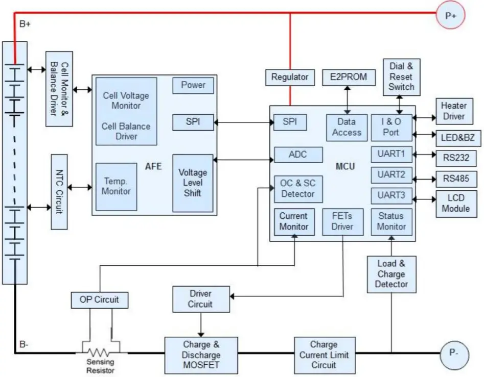 4.2 BMS Parameter
| No. | Item | 51.2V 50Ah |
51.2V 100Ah |
51.2V 150Ah |
51.2V 200Ah |
|
| 1 | Power Consumption | Low power consumption mode | ≤100μA | ≤100μA | ≤100μA | ≤100μA |
| 2 | Over charge Protection | Over charge detection voltage | 3.7V | 3.7V | 3.7V | 3.7V |
| Over charge release voltage | 3.38V | 3.38V | 3.38V | 3.38V | ||
| 3 | Over discharge protection | Over discharge detection voltage | 2.7V | 2.7V | 2.7V | 2.7V |
| Over discharge release voltage | 2.95V | 2.95V | 2.95V | 2.95V | ||
| 4 | Over current protection | Charging over current detection current (detection time) | 27.5A (1S) | 55A (1S) | 82.5A (1S) | 110A (1S) |
| Discharging over current detection current 1 (detection time) |
27.5A 1S |
55A 1S |
82.5A 1S |
110A 1S |
||
| Discharging over current detectioncurrent 2 (detection time) |
≥75A 100ms |
≥150A 100ms |
≥150A 100ms |
≥150A 100ms |
||
| 5 | Temp. Protection | Detection temperature | 65±2℃ | 65±2℃ | 65±2℃ | 65±2℃ |
| 6 | Balance | Balance voltage | 3.55V | 3.55V | 3.55V | 3.55V |
Product Life
The design life of this product is 10 years.
Transportation
During transportation, please keep the battery from acutely vibration, impacting, over-exposure to the sun and drenching.
Storage
7.1 Storage environment requirement
Under temperature of 25±2℃ and relative humidity of 45~85%.
7.2 Storage term
The lithium battery must be charged every six months, and a complete charging and discharging period is required in every nine months.
Cautions
※ The installation and debugging should be operated by professional electric personnel.
※ Please do not stick your hands or other objects deep into the interior of the product.
※ Please do not open the product without a professional around.
※ Please do not mechanically damage the battery module of the energy storage cabinet (perforation, deformation, peeling, etc.).
※ Please use dry powder extinguisher as extinguishing agent.
※ Please do not let the storage cabinet battery module contact abnormal metals or conductors.
※ Please do not use the product after short circuit occurs.
※ Please do not expose the energy storage cabinet to flammable or hazardous chemicals or vapors.
Maintenance Record
Dear user.thank you for selecting our product,Please fill in and keep the warranty card for better services.
Attn: ———-
Product No.: ———-
Tel: ———-
E-mail: ———-
Purchase Date: ———-
| Maintenance Record | |||
| Date of repair | Content | Maintenance Personnel | Note |
![]()