Lutron GCO-2008 Carbon Monoxide Instruction Manual
Contents
FEATURES
- Two function : CO ( Carbon monoxide ), Temperature.
- CO range : 0 to 1,000 ppm x 1 ppm.
- Temperature. : 0 to 50 , / ℃℃℉
- CO measurement with fast response time.
- High repeatability and high accuracy.
- stand-alone device, easy to carryout and operation.
- CO function with alarm setting.
- Large S-TN LCD, high contrast, easy readout.
- Data hold function for freezing the desired value on display.
- Records Maximum and Minimum readings with Recall.
- RS232/USB computer interface.
- Microprocessor circuit assures maximum possible accuracy, provides special functions and features.
- Heavy duty & compact housing with hard carrying case, designed for easy carry out & operation.
- Auto shut off is available to save battery life.
- Power supply from batteries or DC 9V adapter in.
SPECIFICATIONS
| Circuit | Custom one-chip of microprocessor LSI circuit. | |
| Display | LCD size : 52 mm x 38 mmdual function LCD display. | |
| Measurement | CO( Carbon dioxide ), Temperature | |
| Unit | CO | ppm |
| Temp. | ℃, ℉ | |
| Temperature Compensation | Automatic temp. compensation for CO measurement. |
| Advanced Setting | Auto power off enable/disable setting |
| ℃/℉ setting | |
| CO alarm value setting | |
| Alarm Setting | For CO measurement only. |
| Sensor Type | CO : Electrochemical |
| Temperature : Thermister | |
| Data Hold | Freeze the display reading. |
| Memory Recall | Maximum & Minimum value. |
| Display Sampling Time | Approx. 1 second. |
| Power off | Auto shut off saves battery life ormanual off by push button. |
| Zero | Build in zero button for offsetting the zero value |
| Data Output | RS 232/USB PC serial interface.* Connect the optional RS232 cable UPCB-02 will get the RS232 plug.* Connect the optional USB cable USB-01 will get the USB plug. |
| Operating Temperature | 0 to 50 ℃. |
| Operating Humidity | Less than 85% R.H. |
| Power Supply | DC 1.5 V battery ( UM4, AAA ) x 6 PCs,Alkaline/heavy duty type or equivalent. |
| Power Current | Approx. DC 5.6 mA. |
| Weight | 336 g/0.74 LB. @ Battery is included. |
| Dimension | 210 x 68 x 42 mm (8.3 x 2.7x 1.2 inch) |
| Accessories Included | Instruction manual……………… 1 PCSoft carrying case ( CA-05A )….. 1 PC |
| Optional Accessories | RS232 cable, UPCB-02USB cable, USB-01Data Acquisition software, SW-U801-WIN |
Electrical Specifications (23± 5 )
CO ( Carbon dioxide )
|
CO * Carbon monoxide |
Range |
0 to 1,000 PPM |
Resolution |
1 ppm |
|
Accuracy |
± ( 5% + 2 PPM ) |
|
Response time * |
< 30 seconds |
|
Repeatability |
< 2% |
|
Zero drift in long term |
< 5 PPM |
|
Sensitivitydrift |
< 5% per year |
|
* The response time value is specified to reach the 90% reading value. |
||
Temperature
| Temperature | Range | 0 ℃ to 50 ℃,32 ℉ to 122 ℉. | |
| Resolution | 0.1 degree. | ||
| Accuracy | ℃ | ± 0.8 ℃ | |
| ℉ | ± 1.5 ℉. | ||
@ Above specification tests under the environment RF Field Strength less than 3 V/M & frequency less than 30 MHz only.
FRONT PANEL DESCRIPTION

- 3-1 Display
- 3-2 Power Button
- 3-3 Hold Button ( Esc Button )
- 3-4 REC Button ( Enter Button )
- 3-5 Set Button ( Button ) ▲
- 3-6 Alarm Button ( Button ) ▼
- 3-7 Battery Compartment/Cover
- 3-8 Screws for Battery Compartment
- 3-9 Stand
- 3-10 Tripod Fix Nut
- 3-11 RS-232 Output Terminal
- 3-12 DC 9V Power Adapter Input Socket
- 3-13 Reset button.
- 3-14 CO Sensing Head
MEASURING PROCEDURE
CO measurement
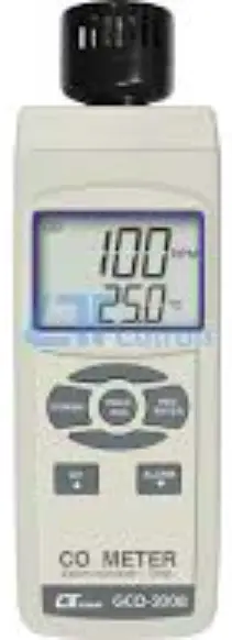
Power on the meter by pressing the ” Power Button “ ( 3-2, Fig. 1 ), wait about 30 seconds to warm up the meter, Display ( 3-1, Fig. 1 ) will show the CO value with the ” PPM ” unit in the upper display, at the same time the lower display will show the Temp. value that sensing from the ” CO Sensing Head ” ( 3-14, Fig. 1 ).

Remark :
- If the measuring environment is not existing the CO value, the upper display will show 0 to 1 ppm. Under open air environment , If Display show few digits CO value, please make the Zero adjustment ” , refer to chapter 8, page 12.
- Response time of CO measurement is < 30 seconds typically, however it is depend on the environment air circulation.
- The Temp. display unit is defaulted to ” “. If ℃ intend to let the meter’s temperature unit default to ” “, please refer to section 5-2 ( page 8 )
Remark :
- If the measuring environment is not existing the CO value, the upper display will show 0 to 1 ppm. Under open air environment , If Display show few digits CO value, please makethe Zero adjustment ” , refer to chapter 8, page 12.
- Response time of CO measurement is < 30 seconds typically, however it is depend on the environment air circulation.
- The Temp. display unit is defaulted to ” “. If ℃ intend to let the meter’s temperature unit default to ” “, please refer to section 5-2 ( page 8 )
Data Hold
During the measurement, press the ” Hold Button “ ( 3-3, Fig. 1 ) once will hold the measured value & the LCD will display a ” HOLD ” symbol.
- Press the ” Hold Button ” once again will release the data hold function.
Data Record ( Max., Min. reading )
- The data record function records the maximum and minimum readings. Press the ” REC Button “ ( 3-4, Fig. 1 ) once to start the Data Record function and there will be a ” REC. ” symbol on the display.
- With the ” REC. ” symbol on the display :
a)Press the ” REC Button ” ( 3-4, Fig. 1 ) once, the ” REC. MAX. ” symbol along with the maximum value will appear on the display. If intend to delete the maximum value, just press the ” Hold Button “ ( 3-3, Fig. 1 ) once, then the display will show the ” REC. ” symbol only & execute the memory function continuously.
b)Press the ” REC Button ” ( 3-4, Fig. 1 ) again, the ” REC. MIN. ” symbol along with the minimum value will appear on the display. If intend to delete the minimum value, just press the ” Hold Button ” ( 3-3, Fig. 1 ) once, then the display will show the ” REC. ” symbol only & execute the memory function continuously.
c) To exit the memory record function, just press the ” REC ” button for 2 seconds at least. The display will revert to the current reading.
ADVANCED SETTING
When execute the following Advanced Setting Procedures should cancel the ” Hold function ” and the ” Record function ” first. The display will not show the ” HOLD ” and the ” REC ” indicator.
Press the ” Set Button ” ( 3-5, Fig. 1 ) continuously at least two seconds will enter the ” Advanced Setting “, then press the ” Button ” ( 3-5, Fig. 1 ) or ” ▲ ▼ Button ” ( 3-6, Fig. 1 ) once a while in sequence to select the three main function, the lower display will show :
PoFF…..Auto power ON/OFF management
t-CF…… Change the Temp , unit ℃ ℉
AL………Setting the CO alarm value
Auto power ON/OFF
When the lower display show ” PoFF ” :
- Press the ” Enter Button ” ( 3-4, Fig. 1 ) once, the upper display will show ” YES “, use the ” Button ” ( 3-5, Fig. ▲ 1 ) or ” Button ” ( 3-6, Fig. 1 ) to select the upper ▼ text to ” no ” or ” YES “. no – Auto Power Off management will disable. YES – Auto Power Off management will enable..
- After select the upper text to ” no ” or ” YES “, press the ” Enter Button ” ( 3-4, Fig. 1 ) will save the setting value ( function ) with default.
- If before press the ” Enter Button “, just press the ” ESC Button ” ( 3-3, Fig. 1 ) will escape the Advanced Setting procedures without saving the value ( function ) into the circuit memory.
Change the Temp , unit ℃ ℉
When the lower display show ” t-CF ” :
- Press the ” Enter Button ” ( 3-4, Fig. 1 ) once, the upper display will show ” C ” or ” F “, use the ” Button ” ▲ ( 3-5, Fig. 1 ) or ” Button ” ( 3-6, Fig. 1 ) to select the ▼ upper text to ” C ” or ” F “.
C – The Temp. unit is . ℃
F – The Temp. unit is . ℉ - After select the upper text to ” C ” or ” F “, press the ” Enter Button ” ( 3-4, Fig. 1 ) will save the setting Temp. unit ( , ) with default. ℃ ℉
- If before press the ” Enter Button “, just press the ” ESC Button ” ( 3-3, Fig. 1 ) will escape the Advanced Setting procedures without saving the value ( function ) into the circuit memory.
Setting the CO alarm value
When the lower display show ” AL ” :
- Press the ” Enter Button ” ( 3-4, Fig. 1 ) once, the upper display will show ” CO alarm value ” with PPM unit, use the ” Button ” ( 3-5, Fig. 1 ) or ” Button ” ( 3-6, ▲ ▼ Fig. 1 ) to select the ” CO alarm value “
- After setting the CO alarm value, press the ” Enter Button ” ( 3-4, Fig. 1 ) will save the setting value with default.
- If before press the ” Enter Button “, just press the ” ESC Button ” ( 3-3, Fig. 1 ) will escape the Advanced Setting procedures without saving the alarm value into the circuit memory.
RS232 PC SERIAL INTERFACE
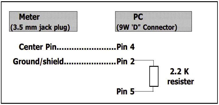
The instrument has RS232 PC serial interface via a 3.5 mm terminal ( 3-11, Fig. 1 ).
The data output is a 16 digit stream which can be utilized for user’s specific application. A RS232 lead with the following connection will be required to link the instrument with the PC serial port.
The 16 digits data stream will be displayed in the following format
D15 D14 D13 D12 D11 D10 D9 D8 D7 D6 D5 D4 D3 D2 D1 D0
Each digit indicates the following status :
| D15 | Start Word = 02 |
| D14 | 4 |
| D13 | When send the upper display data = 1When send the lower display data = 2 |
| D12 &
D11 |
Annunciator for Display | ||
| ℃ = 01 | PPM = 19 | ||
| ℉ = 02 | |||
| D10 | Polarity
0 = Positive |
1 = Negative | |
| D9 | Decimal Point(DP), position from right to the
left 0 = No DP, 1= 1 DP, 2 = 2 DP, 3 = 3 DP |
||
| D8 to D1 | Display reading, D8 = MSD, D1 = LSD
For example : If the display reading is 1234, then D8 to D1 is : 00001234 |
||
| D0 | End Word = 0D | ||
RS232 setting
| Baud rate | 9600 |
| Parity | No parity |
| Data bit no. | 8 Data bits |
| Stop bit | 1 Stop bit |
BATTERY REPLACEMENT
- When the left corner of LCD display show ” “, it is necessary to replace the battery. However, in-spec. measurement may still be made for several hours after low battery indicator appears before the instrument become inaccurate.
- Loose the ” Screws for Battery Compartment ” ( 3-8, Fig. 1 ) take the ” Battery Cover ” ( 3-7, Fig. 1 ) away from the instrument and remove the battery.
- Replace with DC 1.5 V battery ( UM4, AAA, Alkaline/heavy duty ) x 6 PCs, and reinstate the cover.
- Make sure the battery cover is secured after changing the battery.
ZERO ADJUSTMENT
Put the meter into the clean air environment ( not contain any CO value ), power on the meter by pressing the ” Power Button ” ( 3-2, Fig. 1 ), wait about 30 seconds to warm up the meter. If the display not show ” Zero ” CO value, then pressing ” Alarm Button ” ( 3-6, Fig. 1 ) continuously at least two second will offset the display value and show ” 0 PPM “.
- The zero adjustment procedures are effected only existing Display value is within 10 PPM.
SYSTEM RESET
If the meter happen the troubles such as :
CPU system is hold ( for example, the key button can not be operated… ).
Then make the system RESET will fix the problem. The system RESET procedures will be either following method :
During the power on, use a pin to press the ” Reset Button ” ( 3-13, Fig. 1 ) once a while will rest the circuit system, After execute the ” System reset ” the setting value of : Advanced Setting ” will be cleared and return to default value.
CO value via HEALTH INFORMATION
0 to 1 PPM |
General environment |
9 PPM |
Max. exposure time : 8 hours* United States Environmental Protection Agency |
35 PPM |
Max. exposure time : 1 hour* United States Environmental Protection Agency |
50 PPM |
Max. exposure time : 8 hour* OSHA |
100 PPM |
Max. exposure : 100 minutes* Circulation air * UL2034 |
200 PPM |
Headache, tired : Two to three hours |
Max. exposure : 35 minutes* UL2034 |
|
400 PPM |
Headache, tired : One to two hours |
Harm the life : Three hours |
|
Max. exposure : 15 minutes* UL2034 |
|
800 PPM |
Headache, tired : 45 minutes Death : Two to three hours. |
1600 PPM |
Death : One hour. |
Attention :
- Above health information are for reference only.
- The different age, sex, weight and personal heath condition will get the different effecting.