Contents
Algodue UEM63-4D R70 Single Phase Electricity Meter User Manual
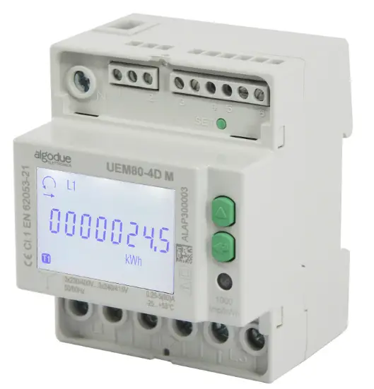
63A THREE PHASE ENERGY METER
The communication protocols and the relevant softwares are available at www.algodue.com
WARNING! Device installation, wiring configuration and terminal cover sealing must be carried out only by qualified professional staff. Switch off the voltage before device installation.
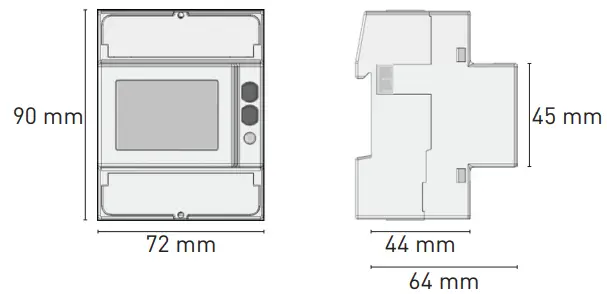
AVAILABLE PACKAGES
| Name | Model | COM port | Nominal voltage, frequency | Available wiring | Tariff input | S0
output |
| (Un, f) | 3.4.3 | |||||
| UEM63-4D R70 | RS485 MODBUS | RS485 | 3×230/400…3×240/415 V,
50/60 Hz |
• | • | • |
The following preset packages are available:
MID: MID certified meter, with reset function only on partial counters.
MID S*: MID certified meter, with reset function only on partial counters, without reactive energy counters on display.
NONE: Meter without MID certification, with reset function only on partial counters.
RESET: Meter without MID certification, with RESET function on ALL counters.
*For MID S package, the device name changes: the S letter is added (e.g. UEM63-4DS R70).
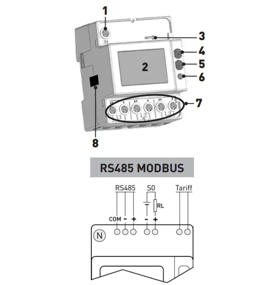
OVERVIEW
Refer to picture B:
- Neutral terminal
- Backlight LCD display
- SET key
- UP key
- ENTER key
- Metrological LED
- Current and voltage terminals
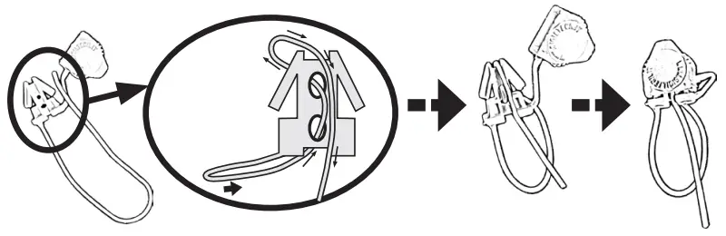
- Safety-sealing (DO NOT REMOVE)
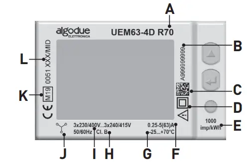
SYMBOLS ON FRONT PANEL (EXAMPLE)
Refer to picture D:
A. Device name
B. Serial number
C. Data Matrix
D. Protection class
E. Meter constant (metrological LED)
F. Base current (max current)
G. Working temperature
H. Accuracy class
I. Nominal voltage/frequency
J. Wiring type: =3phases 4wires 3currents
K. MID approval symbols
L. Type approval certification
If the device is NO MID version, “Cl.1 EN 62053-21” will be shown instead of H, K and L fields.
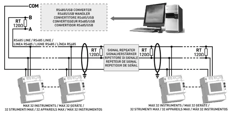
TARIFF INPUT
The RS485 port allows to manage the device by MODBUS RTU/ASCII protocol. For device network connection, install a terminal resistance (RT=120…150 Ω) on the RS485 converter side and another one on the last device connected on the line. The maximum recommended distance for a connection is 1200m at 9600 bps. For longer distances, lower communication speed (bps), low-attenuation cables or signal repeaters are needed. Refer to picture E.
Default values: MODBUS RTU (8N1), 19200 bps
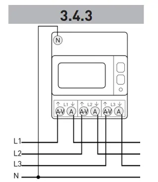
WIRING DIAGRAM
 It is suggested to install a low power switch or some fuses on the voltage inputs for protection and in order to operate on the instrument without deactivating the plant.
Refer to picture F: 3.4.3 = 3 phases, 4 wires, 3 currents
Before instrument power ON, check if all connections are made in a proper way. Make sure that the voltage and current terminals are connected correctly. Moreover, make sure that low voltage ports, such as communication ports and/or SO ports, are connected to low voltage lines. These safety precautions may reduce the risk to damage the instrument in case of improper connections.
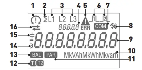
SYMBOLS ON DISPLAY
Refer to picture G:
- Phase sequence: = correct (123), = wrong (132),
- System value
- Value phase number
- Different meanings according to the shown item:
SEtUP: Setup page; InFO: Info page = not defined (e.g. one or more phases are missin - Metrological parameters corrupted (Code: XX). Useless counter, to be returned to the Manufacturer
- S0 output active status
- Communication active status
- Setup page
- Main area
- Measuring unit area
- Partial counter Flashing=stopped counter
- 1 or 2 tariff counter value
- Balance counter value
- Inductive value
- Capacitive value
- Imported (>), exported (<) energy or power value
MEASUREMENTS
| SYMBOL | MEASURE UNIT | DISPLAY | PORT | |
| INSTANTANEOUS VALUES |
V∑, V1, V2, V3 |
V |
|
l |
| Voltage | ||||
| Line voltage | V12, V23, V31 | V | l | |
| Current | I∑, I1, I2, I3, IN | A |
|
n |
| Power factor | PF∑, PF1, PF2, PF3 | – | l | |
| Apparent power | S∑, S1, S2, S3 | kVA | n | n |
| Active power | P∑, P1, P2, P3 | kW | n | n |
| Reactive power | Q∑, Q1, Q2, Q3 | kvar | n
|
n |
| Frequency | f | Hz | l | |
| Phase sequence | CW / CCW | – | l | l |
| Power direction | ⮀ | – | l | l |
| RECORDED DATA | ||||
| Total active energy | ∑, L1, L2, L3 | kWh | n | n |
| Total ind. and cap. reactive energy | ∑, L1, L2, L3 | kvarh | nv | n |
| Total ind. and cap. apparent energy | ∑, L1, L2, L3 | kVAh | n | n |
| Tariff 1-2 energy counters | T1 T2 ∑, L1, L2, L3 | kWh, kvarh, kVAh | nv | n |
| Resettable partial energy counters | PAR ∑ | kWh, kvarh, kVAh | nv | n |
| Energy balance | BAL ∑ | kWh, kvarh, kVAh | nv | n |
| OTHER INFORMATION | SYMBOL | STATUS | DISPLAY
|
PORT |
| Present tariff | T1, T2 | – | l | |
| Undervoltage/overvoltage | AL | – | l | |
| Undercurrent/overcurrent | AL | – | l | |
| Frequency out of range | AL | – | l | |
| Partial counter status | PAR / PAR | Started / Stopped | l | l |
| S0 output status | Active | l |
All the system counters (kWh∑, kvarh∑, kVAh∑) can be associated to S0 output.
PICTURE/ABBILDEN/FIGURA/FIGURE/IMAGEN
B
C
D
E
F
D
Read More About This Manual & Download PDF: