![]() INSTALLATION Accessories – Q-VAULT-5
INSTALLATION Accessories – Q-VAULT-5
Contents
QSET-180 Low Voltage Luminaire Power Supply
•3426-94 Luminaires – Landscape Lighting Systems – Certified to UL – 1838 Standard.•3425-95 Luminaires – Low Voltage Lighting Systems – Certified to UL – 2108 Standard. •3425-96 Luminaires – Component Hydromassage – Certified to UL – Pool & Spa Standard.
|
|
• 3425-15 Luminaires – Low Voltage Lighting Systems. |
![]()
- For supply connections use wire rated for at least 90°C
- Suitable for in-ground installation
- Use dimmers rated for magnetic low voltage load
- ot for installation to conduit extending directly to an underwater pool light forming shell.
- Use dimmers rated for appropriate lighting load.
- Suitable for use with submersible luminaires
- Suitable for indoor & outdoor use
- Warning: risk of fire – if installation involves running wiring through a building structure, special wiring methods are needed. Consult National and Local Codes.
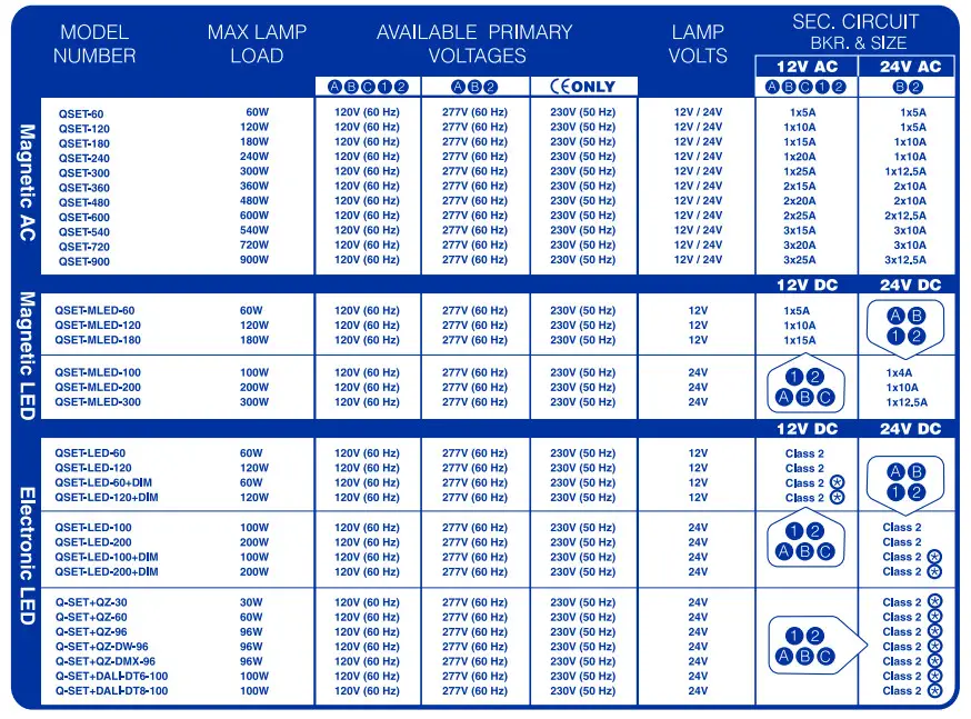
Q-SET LOW VOLTAGE LUMINAIRE POWER SUPPLY
| MODEL NUMBER | OUTPUT CLASS | MAX LAMP LOAD | PRIMARY VOLTS | LAMP VOLTS | DIMMER RATING | SEC. 12V | BREAKERS 24V |
| QSET-180 QSET-240 QSET-300 QSET-360 QSET-480 QSET-600 QSET-540 QSET-720 QSET-900 |
CLASS 1 CLASS 1 CLASS 1 CLASS 1 CLASS 1 CLASS 1 CLASS 1 CLASS 1 CLASS 1 |
180W 240W 300W 360W 480W 600W 540W 720W 900W |
120V/277 (60Hz) 120V/277 (60Hz) 120V/277 (60Hz) 120V/277 (60Hz) 120V/277 (60Hz) 120V/277 (60Hz) 120V/277 (60Hz) 120V/277 (60Hz) 120V/277 (60Hz) |
12V/24V 12V/24V 12V/24V 12V/24V 12V/24V 12V/24V 12V/24V 12V/24V 12V/24V |
MLV MLV MLV MLV MLV MLV MLV MLV MLV |
1X15 1X20 1X25 2X15 2X20 2X25 3X15 3X20 3X25 |
1X7.5 1X10 1X12.5 2X7.5 2X10 2X12.5 3X7.5 3X10 3X12.5 |
| QSET-ELED-60 QSET-ELED-120 QSET-ELED-60/0-10 QSET-ELED-120/0-10 QSET-ELED-100 QSET-ELED-200 QSET-ELED-100/0-10 QSET-ELED-200/0-10 |
CLASS 2 CLASS 2 CLASS 2 CLASS 2 CLASS 2 CLASS 2 CLASS 2 CLASS 2 |
1X60=60W 2X60=120W 1X60=60W 2X60=120W 1X100=100W 2X100=200W 1X100=100W 2X100=200W |
12V/24V 12V/24V 12V/24V 12V/24V 12V/24V 12V/24V 12V/24V 12V/24V 12V/24V |
12V/24V 12V/24V 12V/24V 12V/24V 12V/24V 12V/24V 12V/24V 12V/24V 12V/24V |
NO NO 0-10 0-10 NO NO 0-10 0-10 |
12V 12V 12V 12V – – – – |
24V 24V 24V 24V |
| QSET-MLED-60 QSET-MLED-120 QSET-MLED-180 QSET-MLED-100 QSET-MLED-200 QSET-MLED-300 |
CLASS 1 CLASS 1 CLASS 1 CLASS 1 CLASS 1 CLASS 1 |
60W 120W 180W 100W 200W 300W |
12V 12V 12V 12V 24V 24V 24V 24V |
12V 12V 12V 24V 24V 24V |
MLV MLV MLV MLV MLV MLV |
12V 12V 12V – -_ |
24V 24V 24V |
CSA LISTING
| SET-180 QSET-240 QSET-300 QSET-360 QSET-480 QSET-600 QSET-540 QSET-720 QSET-900 |
OUTDOOR Under 15 Volts = LV Wire Burried 0” to 6” Outdoor Landscape Lighting – Under 15 Volts CSA Certified for both the U.S. and Canada to the UL-1838 Standard for Landscape Lighting with in-ground enclosure and component power supply operating at less than 15V. This listing allows for the LV Q-WIRE to be installed 0” to 6” underground. Pool & Spa – Under 15 Volts CSA Certified for the U.S. to the UL-Pool & Spa Power Supply Standard. This listing is intended for power supplies used to power fountain, swimming pool and spa luminaires operating at less than 15V. |
|
| QSET-ELED-60 QSET-ELED-120 QSET-ELED-60/0-10 QSET-ELED-120/0-10 QSET-ELED-100 QSET-ELED-200 QSET-ELED-100/0-10 QSET-ELED-200/0-10 |
OUTDOOR 15 to 30 Volts = LV Wire burried 18” Outdoor Landscape Lighting – 15 to 30 Volts CSA Certified for both the U.S. and Canada to UL-2108 Standard with a listing of “Low Voltage Luminaire Power Supply” for lamps operating at 12 or 24 volts where the secondary voltage is between 15 to 30 volts. Please note that the secondary wiring must be installed 18” below grade per the N.E.C. |
|
| QSET-MLED-60 QSET-MLED-120 QSET-MLED-180 QSET-MLED-100 QSET-MLED-200 QSET-MLED-300 |
INDOOR LV Lighting under 30 Volts Indoor Open Conductor Systems – Under 30V CSA Certified for both the U.S. and Canada to UL-2108 Standard as a “Low Voltage Luminaire Power Supply” for lamps operating at 12V or 24V allows for live conductor lighting equipment mounted above 7 feet and other types of LV Lighting equipment, per N.E.C. Article 411. When tested in conjunction with open conductor lighting system. |
NOTE: Refer to the last page.
Q-VAULT 120V (60HZ) – 12V
FOR CONDUIT CONNECTION
WARNING – RISK OF SHOCK. Install power unit 5 feet (1.5 m) or more from the pool or spa and 10 feet (3.05 m) or more from a fountain. Where the power unit is installed within 10 feet (3.05 m) of a pool or spa, connect unit to GFCI protected branch circuit.
FOR POWER SUPPLY CORD CONNECTION WARNING
– RISK OF SHOCK. Installed power unit 5 feet (1.5M) or more from the pool, spa, or fountain. Where the power unit is installed (a) indoors within 10 feet (3.05) of a pool, spa, or fountain or (B) outdoors, connect power unit to a receptacle protected by a GFCI. WARNING – RISK OF FIRE. If installation requires running wire through
a building structure, special wiring methods are needed. Contact a qualified electrician.
WARNING – Do not use extension cords.
The main Secondary Wiring is intended for shallow burial – less than 6 inches (152 mm) For Supply connections use wire rated for at least 60C.
- SUITABLE FOR INDOOR / OUTDOOR USE
- SUITABLE FOR USE WITH SUBMERSIBLE LUMINAIRES OR SUBMERSIBLE PUMPS • SUITABLE FOR USE WITH LOW VOLTAGE LANDSCAPE
LUMINAIRES / FITTINGS
Q-VAULT 277V (60HZ) – 12V (US Only)
WARNING – RISK OF SHOCK. Install power unit 5 feet (1.5 m) or more from the pool or spa and 10 feet (3.05 m) or more from a fountain. Where the power unit is installed within 10 feet (3.05 m) of a pool or spa, connect unit to GFCI protected branch circuit.
WARNING – Outdoor Cord-connected unit shall be connected to a GFCI protected hooded flush type cover plate recepticle marked “Wet Location
The main Secondary Wiring is intended for shallow burial – less than 6 inches (152 mm)
For Supply connections use wire rated for at least 60C.
- SUITABLE FOR INDOOR / OUTDOOR USE
- SUITABLE FOR USE WITH SUBMERSIBLE LUMINAIRES OR SUBMERSIBLE PUMPS
- SUITABLE FOR USE WITH LOW VOLTAGE LANDSCAPE LUMINAIRES / FITTINGS
CONTACT YOUR LOCAL DISTRIBUTOR OR Q-TRAN FOR Q-WIRE, Q-CLIK OR PROPER ACCESSORY KITS.
ROUGH IN WIRING
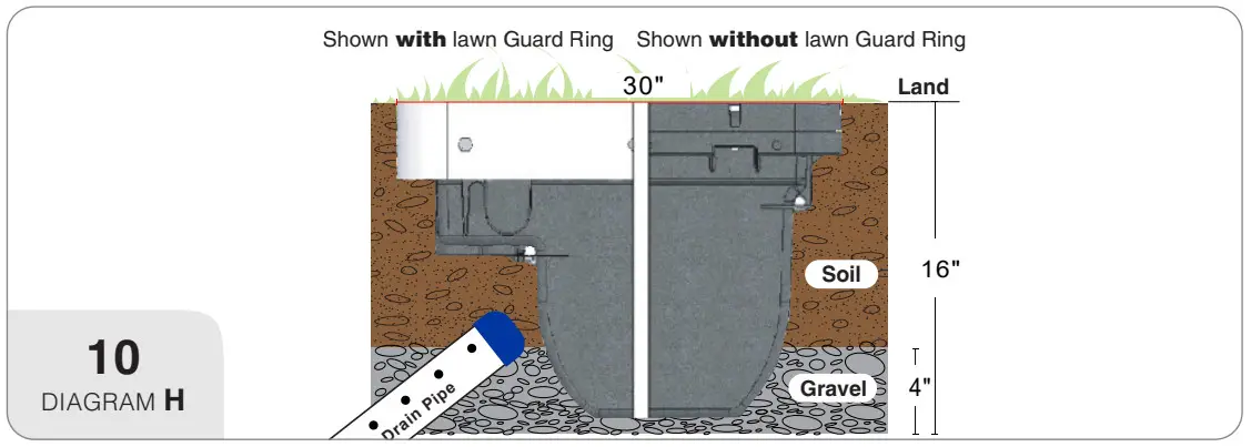
- Excavate a 14” x 30” x 16” deep hole for the Q-VAULT direct burial housing.
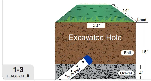
- Dig trenches for primary & secondary wiring to Q-VAULT housing location.
- Place drain pipe at a 30 degree angle at the lowest slope of land for proper drainage. Fill bottom of pit with a minimum of 4″ of gravel. SEE DIAGRAM A
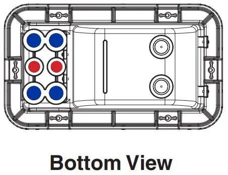
Note: Increase width to 30” x 30” when stabilizing bars are used. - Bring all primary and secondary wiring into housing. A: Entry location is provided at both the bottom and side of the Junction Box located on the Q-VAULT housing.
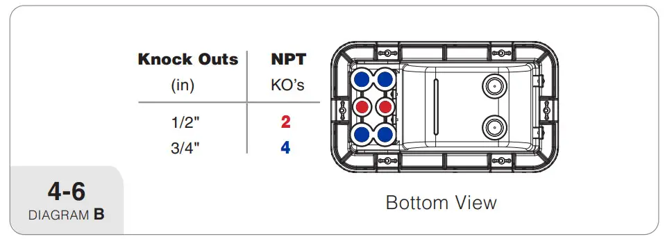
B: On the bottom of Junction Box there are: (4) 3/4” NPT an(2) 1/2” NPT KO’s. SEE DIAGRAM B
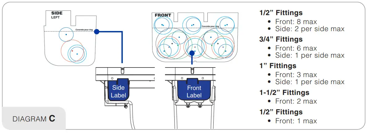
C: Using the Field Drill Guide Labels provided in the installation kit you are able to drill for various fitting sizes. Only knock out openings for conduits being utilized in installation. SEE DIAGRAM C - After all field wiring has been installed with proper lead lengths, tighten all fittings properly to assure they are water proof. All drilled entries require Q Click wire connectors to insure water tight connection. Use of other connectors voids warranty.
- Coil and store field wiring in Junction Box area.
Note: Label all wiring for future reference.
FOR COMPLETE WATER TIGHT GUARANTEE
PRIMARY WIRING IN (120-277V)Conduit – Use Installation Kit
• Step 1: Putty
• Step 2: Epoxy
• Step 3: Syringe
Non-conduit – use Q-CLIK NPT.75, Q.750-1E, Q-WIRE 12/3
SECONDARY WIRING OUT (12-24V)
Low voltage wire (non-conduit)
• Q-CLIK
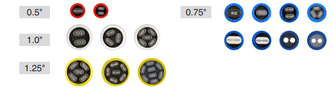
• NPT-or knock outs in bottom of Q-VAULT, .5-.75
• MST to drill into the side of the housing, .5-1.25
• Q-WIRE low voltage marine grade UFB wire (recommended)
10-14AWG
• Standard Q-CLIK insert
Conduit – low voltage, requires Seal Kit (sold separately)
• Step 1: Putty
• Step 2: Epoxy
• Step 3: Syringe - Clean debris from the top perimeter and install gasket. SEE DIAGRAM D
-
Install door and tighten the 6 door bolts in the number sequence shown. SEE DIAGRAM E
Note: Nut driver can be used to get bolts seated before final tightening. Proper door bolt tightening must be done with a ratchet wrench using a 3/8“ socket at a maximum torque of 50 in-lbs. - Attach the provided Support Bars to the Q-VAULT housing using the 6-32 X 5/8 screws. SEE DIAGRAM F
- Level housing and fill hole with gravel to 4“ of below grade. Add soil to surface. SEE DIAGRAM H
All wire entry/exits other than conduit entries MUST use Q-CLIK connectors. Failure to use them will void warranty. - Remove cover if installed, be sure to store cover and cover gasket in a clean and dry location.
- Move field wiring out of the way.
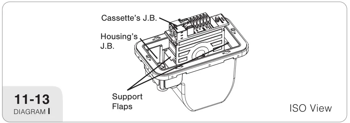
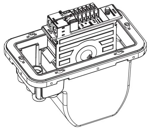
- Place Q-SET low voltage luminaire power supply cassette into the 11 12 13 Q-VAULT housing using the support flaps. The cassette’s primary junction box should be placed next to field wiring junction box located on the housing. SEE DIAGRAM I
-
Landscape Lighting: Landscape Lighting:
Bring primary field wiring directly into the Cassette’s primary junction box through open hole.
Pool & Spa: Bring primary field wiring through the P&S sleeving. Do n screw base fitting to field junction box until re-enterable potting is complete. SEE DIAGRAM J Call Q-Tran (203-367-8777) if P&S sleeving is needed. Primary Connections: – Ground Green terminal – Neutral to White terminal – Hot to either: Tap1 – No Dimmer / Tap2 – With Dimmer
A: For proper connection to terminal block, use the Strip Length Guide n the primary junction box cover of the Cassette. Determine the strip length pproximately 1”.
B: Using supplied hex key unscrew wire(s) and hand tighten the (2)1/4-28 316ss set screws.
C: Fully insert the properly stripped wire(s) and hand tighten both set screws with provided hex key. Do Not use a ratchet wrench. Maximum torque = 30 in-lbs. SEE DIAGRAM K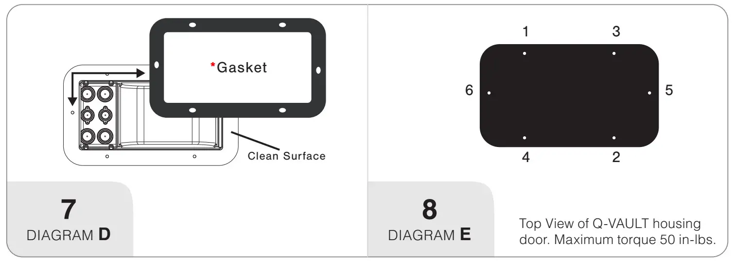 *Gasket only fits one way. Gasket easily slides over Q-VAULT posts. If you are having to force the gaskeit is backwards (Gasket must sit on top of Q-VAULT. No portion should be overhanging).
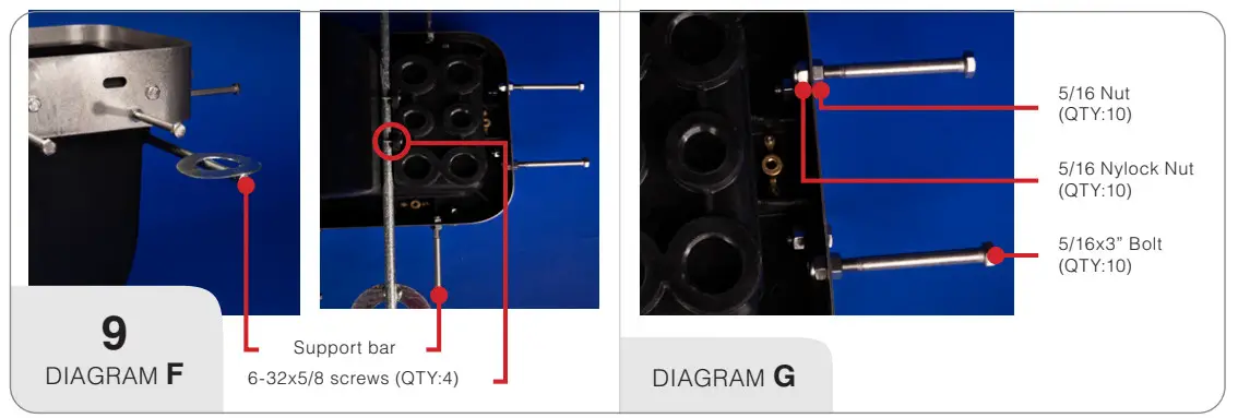
Note: See page 7 for re-enterable potting steps.
Terminal Capacity
Solid or Stranded
7 – #14 AWG Wires
5 – #12 AWG Wires
4 – #10 AWG Wires
2 – #8 AWG WiresHOUSING
HOUSING DOOR: Underside View
 HOUSING: Outside View
Hole Drill Guide Label: Refer to sticker instructions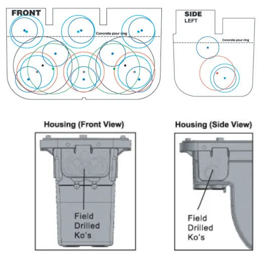
INSTALLING Q-SET 1, 2, 3
- Determine proper lengths and trim to correct length.
- Low Voltage Common: Is connected to a yellow terminal block which is internally wired to a secondary breaker.
- Low Voltage Line: Is connected to 1 of the 5 taps
Note: Unless the proper tap is known, always connect to the terminal marked START. For multiple secondary runs repeat steps.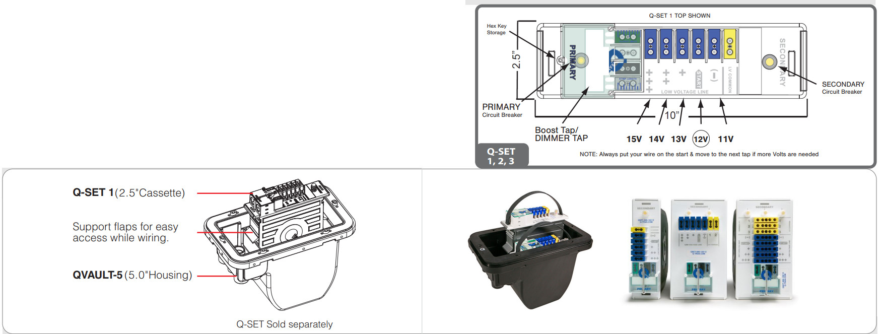
Note: Assemble Part Q-Vault only with part
• QSET-900/ -750/ -720/ -600/ -540/ -480/ -360/ -300/ -240/ -180
• LED-60/ -LED-100/ -LED-120/ -LED-160/ -LED-200
• MLED-300/ -MLED-200/ -MLED -100/ -MLED-180/ -MLED-120/ -MLED-60
INSTALLING Q-SET-eLED
-
Upon completion of all field wiring lift cassette up slightly to allow suppflaps to drop and lower cassette into the housing.
- Using wire ties provided secure field wiring to cassette using the slots provided on the primary junction box cover and junction box sides. SEE DIAGRAM L Secure primary junction box cover and store hex key.
- SEE DIAGRAM M (Potting Field Connections)
-
First properly locate all field wiring inside the junction box where it will bpermanently positioned

INSTALLING Q-SET-mLED


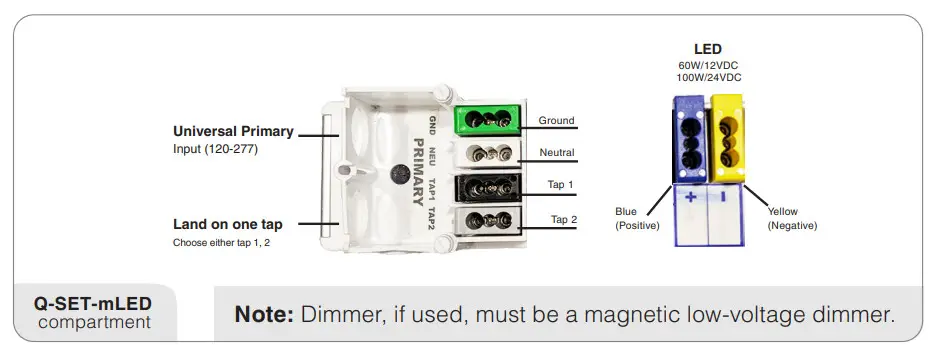
SIMPLE AS 1, 2, 3
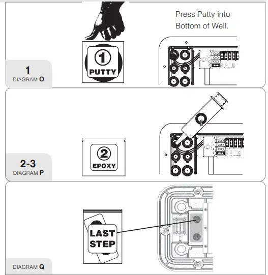
- Use putty provided to seal wires in potting well. It is important that the well is liquid tight so that when the re-enterable epoxy is poured, it does not escape out the bottom. Be sure the putty is put into the very bottom of the well to allow ample room for the epoxy. SEE DIAGRAM O
- A: The 3M-8882 re-enterable epoxy takes several hours to set. When set it will form a into a water tight “jello” consistency.
B: Mix the two part epoxy together per 3M instructions located on the epoxy packaging.
C: Push all the mixed epoxy together to one end of the bag. Cut the corner of the bag. - A: Using the syringe pull the mixed epoxy into the syringe by pulling the plunger out slowly.
B: Slowly dispense the mixed epoxy from the syringe into the utilized potting wells. SEE DIAGRAM P
Note: Potting is now complete
LAST STEP
Final Door Installation
- Clean housing area where door gasket will rest
- Reinstall clean door gasket.
Before Door is Installed
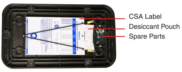
Put velcro desiccant bag in place. Attach the two velcro loop coins on the desiccant bag to the two velcro hook coins on the underside of the housing door. SEE DIAGRAM Q
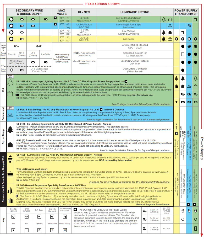
NEC CODE & UL STANDARDS FOR LIGHTING Systems Operating at 30 Volts or Less
![]()
 QVAULT-5 USE ONLY WITH Q-TRAN Q-SET POWER SUPPLY
![]() A 3426-94 Luminaires – Landscape Lighting Systems – Certified to UL – 1838 Standard.
A 3426-94 Luminaires – Landscape Lighting Systems – Certified to UL – 1838 Standard.
![]() B 3425-95 Luminaires – Low Voltage Lighting Systems – Certified to UL – 2108 Standard.
B 3425-95 Luminaires – Low Voltage Lighting Systems – Certified to UL – 2108 Standard.
C 3425-96 Luminaires – Component Hydromassage – Certified to UL – Pool & Spa Standard.
1 3426-04 Luminaires – Landscape Lighting Systems – Component (including Hydromassage).
2 3425-15 Luminaires – Low Voltage Lighting Systems.
![]() INDEPENDENT 0-10V DIMMER, MLV/ELV DIMMER, DMX CONTROL OR DALI CONTROL
INDEPENDENT 0-10V DIMMER, MLV/ELV DIMMER, DMX CONTROL OR DALI CONTROL
![]() For Supply CONNECTIONS use WIRE RATED FOR AT LEAST 90°C
For Supply CONNECTIONS use WIRE RATED FOR AT LEAST 90°C
![]() POUR LES CONNEXIONS D’ALIMENTATION, UTILISEZ UN FIL EVALUE A 90°C AU MOINS
POUR LES CONNEXIONS D’ALIMENTATION, UTILISEZ UN FIL EVALUE A 90°C AU MOINS
![]() For ound wstarration ony
For ound wstarration ony
![]() POUR INSTALLATION AU SOL UNIQUEMENT
POUR INSTALLATION AU SOL UNIQUEMENT
NOTFOR INSTALLATION To A CONDUIT EXTENDING DIRECTLY TO AN UNDERWATER POOL LIGHT FORMING SHELL
![]() NE PAS INSTALLER SUR UN CONDUIT SIETENDANT DIRECTEMENT SUR UN ENVELOPPE DE LUMIERE DE PISCINE SOUS L’EAU
NE PAS INSTALLER SUR UN CONDUIT SIETENDANT DIRECTEMENT SUR UN ENVELOPPE DE LUMIERE DE PISCINE SOUS L’EAU
![]() PRIMARY TERMINAL MARKED WITH IDENTIFICATION MARKINGS BLACK FOR LINE, WHITE FOR NEUTRAL, GREEN FOR GROUND
PRIMARY TERMINAL MARKED WITH IDENTIFICATION MARKINGS BLACK FOR LINE, WHITE FOR NEUTRAL, GREEN FOR GROUND
![]() BORNE PRIMAIRE MARQUEE AVEC DES MARQUAGES D’IDENTIFICATION NOIR POUR LA LIGNE, BLANC POUR LE NEUTRE, VERT POUR LA TERRE
BORNE PRIMAIRE MARQUEE AVEC DES MARQUAGES D’IDENTIFICATION NOIR POUR LA LIGNE, BLANC POUR LE NEUTRE, VERT POUR LA TERRE
![]() USE DIMMERS RATED FOR ELECTRONIC OR MAGNETIC LOW VOLTAGE LOAD IF THE POWER UNIT IS ELECTRONIC OR MAGNETIC
USE DIMMERS RATED FOR ELECTRONIC OR MAGNETIC LOW VOLTAGE LOAD IF THE POWER UNIT IS ELECTRONIC OR MAGNETIC
UTILISEZ DES GRADATEURS CONCUS POUR UNE CHARGE ELECTRONIQUE OU MAGNETIQUE A BASSE TENSION SI L’UNITE D’ALIMENTATION EST ELECTRONIQUE OU MAGNETIQUE
suraste For use wis suBMERsiBLE LUMINARIES
ADAPTE AUX LUMINAIRES SUBMERSIBLES
sumste ron inoo0r & ourooor use
ADAPTE AL’USAGE INTERIEUR ET EXTERIEUR
swiss. ror wer ocarions
ADAPTE AUX ENDROITS HUMIDES
warning: hisk oF rine – tf NSTALLATION INVOLVES RUNNING WIRING THROUGH A BUILOING STRUCTURE, SPECIAL WIRING METHODS ARE NEEDED. CONSULT A QUALIFIED ELECTRICIAN.
AVERTISSEMENT: RISQUE D’INCENDIE – SI INSTALLATION IMPLIQUE DE RACCORDER UN CABLAGE A TRAVERS UNE STRUCTURE DE BATIMENT, DES PROCEDES DE CABLAGE SPECIAUX SONT NECESSAIRES. CONSULTER UN ELECTRICIEN QUALIFIE.
![]() USE ONLY WITH MAXIMUM 30 WATT LAMP LOAD FOR MODELS CISET+OZ-30
USE ONLY WITH MAXIMUM 30 WATT LAMP LOAD FOR MODELS CISET+OZ-30
UTILISER UNIQUEMENT DES AMPOULES DE 30 W MAX, DE TYPE O-SET+OZ-30
USE ONLY WITH MAXIMUM 60 WATT LAMP LOAD FOR MODELS Q-SET+OZ-60
UTILISER UNIQUEMENT DES AMPOULES DE 60 W MAX, DE TYPE (ISET+OZ-60
USE ONLY WITH MAXIMUM 96 WATT LAMP LOAD FOR MODELS O•SET+OZ-96,
Q•SET+OZ-D1µ96, O.SET+OZ•DMX-96, (1-SET+DALI-DT6.100, CISET+DAUDT8-100 UTILISER UNIQUEMENT DES AMPOULES DE 96 W MAX, DE TYPE O-SET+OZ-96, O-SET+QZ-DW-96, O-SETOZ-DMX-96, OSET+DALI-DT6-100, O-SET+DALI-DT8-
READ INSTALLATION INSTRUCTIONS
www.q-tran.com
© 2023 Q-Tran Inc. All rights reserved
155 Hill St. Milford, CT 06460
203-367-8777
[email protected]
www.q-tran.com
Specification subject to change. Rev-06-26-23