Contents
COMSTAR DVC-20 Interface Device

Update Table
| Version | Changelist | Author | Date |
| V1.0 | First Version | WURUI | 2022/12/15 |
| Reviewer:Peng Yincan | |||
Attention
Brand: Product name and brand mentioned in this user’s guide are the property of the company.
Notices
- Please read the instructions in detail before using the motherboard to avoid damaging the motherboard by wrong operation.
- Please store or use the product in the environment of -10℃ <=Work Station <=+50 ℃, 95%RH, to avoid damaging the product for too hot or cold.
- Please do not do strongly mechanical shake, and do not operate the product before ESD protection.
- Please disconnect all power cables from the existing system before you add or remove a device.
- Make sure your power supply is set to correct voltage, namely DC 12V
- Forbid to repair, modify or alter the product by self. If it causes any damage, we don’t take any responsibility.
specifications
| Main features | |
| Processor | Intel Apollo Lake-D J3455 Intel® Celeron® Processor (TDP 10W)① |
| Memory | 4G DDR3L-1600MT/s |
|
Storage |
1×M.2 2280 M-Key
16GB EMMC |
|
Network |
4×RJ45 Gigabit Ethernet Interfaces (Ethernet Controller: Realtek 8111H) |
| WNFQ-258ACN(BT) | |
| Extension features | |
|
IO interface |
1×HDMI 2.0 Display Port (Max Resolution:4096×2160@60Hz) |
| 4×RJ45 Gigabit Ethernet Interface | |
| 2×USB3.0 Ports | |
| 4× Serial Ports(COM1 supports TTL,COM2 supports RS232,COM3&4 supports RS232/485 selections) | |
| 1*LINE-OUT | |
| 1*CEC-IR | |
| 1*KNX | |
| 2×Reserved antenna holes | |
| Extension Slots | 1×M.2 2230 E-Key for WIFI & Bluetooth Module extension |
| System features | |
| O.S | Ubuntu |
|
Power Supply |
12V/7.5A DC Input |
| DC2.5 metal threaded joint | |
| Mechanical features | |
| Materials | SGCC |
| Dimensions | 227mm(L)×116.2mm(W)×37.4mm(H) |
| Installation | Wall mount |
| Operating environment | |
|
Temperature |
Operating temperature:-10℃~+50℃
Storage temperature:-40℃~+85℃ |
| Relative humidity | Power Off: 95%,does not condense at 25 to 30 temperatures |
Notice:
①J3455: 4-core 4-thread, 1.5GHz main frequency, graphics:Intel® HD Graphics 500
Product view
Product pictures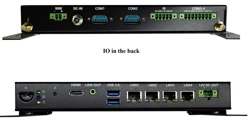
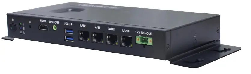
Side view
Physical dimensions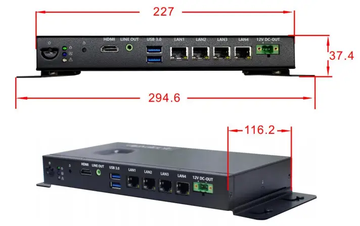
Notice: The dimensions in the drawing are uniform in millimeters(mm).
Interface Introduce
Function indication diagram of chassis interface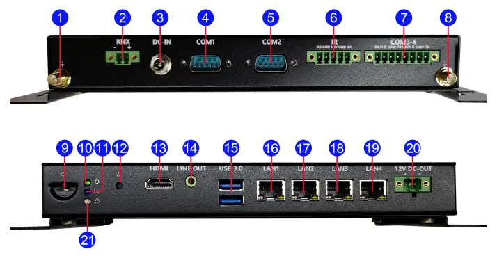
Interface Description
- Reserved antenna hole
- 2 3.81-2pin KNX Terminals
- DC2.5 metal threaded joint
- DB9 Serial Port 1
- DB9 Serial Port
- 2 3.81-5pin CEC_IR Terminals
- 3.81-8pin Terminals(COM3~COM4)
- Reserved antenna hole 1
- Power button Power status indicator
- LED(green,on)
- Network connection light
- System reset button
- HDMI 2.0b display Port
- LINE-OUT audio output interface
- Double layer USB3.0 Type-A
- Port RJ45 Gigabit Ethernet 1
- RJ45 Gigabit Ethernet 2 RJ45
- Gigabit Ethernet 3
- RJ45 Gigabit Ethernet 4 5.08-2pin
- DC-OUT Terminals
- Abnormal display indicator LED
Pin Definition
COM1~4 Serial Ports
Notice: COM1 supports TTL: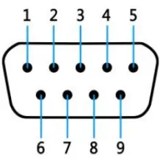
| pin# | Signal | pin# | Signal |
| 1 | 6 | DV-ICE | |
| 2 | TTL_RXD | 7 | |
| 3 | TTL_TXD | 8 | |
| 4 | 9 | ||
| 5 | GND |
Notice: COM2 supports RS232
| pin# | Signal | pin# | Signal |
| 1 | 6 | DV-ICE | |
| 2 | 232_RXD | 7 | |
| 3 | 232_TXD | 8 | |
| 4 | 9 | ||
| 5 | GND |
Notice: COM3、COM4 can select RS232/RS485 by Setting BIOS parameters. The Pin definitions are shown in the table below:
|
pin |
Pin definitions | |
| RS232 | RS485 | |
| 1 | DCD | D- |
| 2 | SIN | D+ |
| 3 | SOUT | |
| 4 | DTR | |
| 5 | GND | GND |
| 6 | DSR | |
| 7 | RTS | |
| 8 | CTS | |
| 9 | RI | |
HDMI Interface
Use standard HDMI definition, omitted here.
USB Interface
Use standard USB Type-A definition, omitted here.
Audio Interface
LINE-OUT Use standard 3.5mm audio interface definition, omitted here.
KNX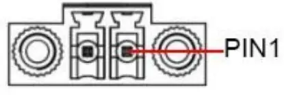
| JP/CN | pin# | Signal |
|
KNX |
1 |
KNX- |
|
2 |
KNX+ |
IR
| JP/CN | pin# | Signal |
|
IR |
1 |
IR2 |
|
2 |
GND |
|
|
3 |
+3.3V |
|
|
4 |
GND |
|
|
5 |
IR1 |
DC-OUT
| JP/CN | pin# | Signal |
|
DC_OUT |
1 |
12V |
|
2 |
GND |
DC-IN
| JP/CN | pin# | Signal |
|
DC_IN |
1 | 12V |
| 2 | GND |
FCC Warning
This device complies with part 15 of the FCC rules. Operation is subject to the following two conditions: (1) this device may not cause harmful interference, and (2) this device must accept any inte rference received, including interference that may cause undesired operation.
Changes or modifications not expressly approved by the party responsible for compliance could void the user’s authority to operate the equipment.
NOTE: This equipment has been tested and found to comply with the limits for a Class B digital device, pursuant to part 15 of the FCC Rules. These limits are designed to provide reasonable protection against harmful interference in a residential installation. This equipment generates uses and can radiate radio frequency energy and, if not installed and used in accordance with the instructions, may cause harmful interference to radio communications. However, there is no guarantee that interference will not occur in a particular installation. If this equipment does cause harmful interferenceto radio or television reception, which can be determined by turning the equipment off and on, the user is encouraged to try to correct the interference by one or more of the following measures:
- Reorient or relocate the receiving antenna.
- Increase the separation between the equipment and receiver.
- Connect the equipment into an outlet on a circuit different from that to which the receiver is connected.
- Consult the dealer or an experienced radio/TV technician for help.
Radiation Exposure Statement
This equipment complies with FCC radiation exposure limits set forth for an uncontrolled environment. This equipment should be installed and operated with minimum distance 20cm between the radiator and your body.
Shenzhen Comstar Technology Co.,Ltd