![]() Ceiling Cassette
Ceiling Cassette
Ductless Mini-Split and Chilled Water
Technical ManualModels CSD, CSH and CCW
Contents
OVERVIEW / TABLE OF CONTENTS
Overview
The ceiling mounted Cassette units effectively make each area served an independent controlled temperature zone. Through thermostatic control of operations, conditions can be varied to suit diverse requirements or activities. Optional fresh air intakes are available to provide outside air for ventilation into the space.
Cassettes are available in a choice of three models: DX cooling, heat pump, or chilled water cooling. Optional heating can be provided as electric heat or hot water, depending on the model.
This versatility eliminates compromising architecture or design. Important cost savings are often realized during building modernizations, as existing piping and/or wiring can frequently be reused.
Design techniques are incorporated in every Airedale by Modine Cassette to reduce noise levels to a minimum. These techniques include low blower speeds, rigid panel and cabinet construction, and sound-absorbent cabinet insulation.
For individual comfort, Cassettes are available with electromechanical or micro-processor based controls.
The microprocessor controller includes an infrared transmitter which enables room conditions to be maintained at a user defined setpoint.
The Cassettes are also available with Carrel microprocessor controls and network cards to allow units to be connected to a Building Management System.
![]() The Modine Breeze® AccuSpec is the fastest way to generate performance data based on actual job conditions. The Breeze® AccuSpec program is a web-based sizing and selection program. The program provides a series of step-by-step questions that allow for the easy configuration of Airedale by Modine products. After a model has been configured, the program can generate Submittal Schedules, Submittal Data (including performance and dimensional
The Modine Breeze® AccuSpec is the fastest way to generate performance data based on actual job conditions. The Breeze® AccuSpec program is a web-based sizing and selection program. The program provides a series of step-by-step questions that allow for the easy configuration of Airedale by Modine products. After a model has been configured, the program can generate Submittal Schedules, Submittal Data (including performance and dimensional
drawings), and Specifications.
MODEL IDENTIFICATION
Model Nomenclature
| 1 | 2,3 | 4,5 | 6 | 7 | 8 | 9 | 10 | 11 | 12 | 13 |
| PT | UC | MBH | SV | G | C | HO | FL | FP | PO | CC |
1 – Product Type (PT)
C – Ceiling Cassette
2,3 – Unit Configuration (UC)
SD – DX Cooling
SH – HP Heating and Cooling
CW – Chilled Water
4,5 – Nominal Capacity (MBH)
08 – 8,000 Btu/Hr
12 – 12,000 Btu/Hr
18 – 18,000 Btu/Hr
20 – 20,000 Btu/HR
24 – 24,000 Btu/Hr
30 – 30,000 Btu/Hr
33 – 33,000 Btu/Hr
36 – 36,000 Btu/Hr
42 – 42,000 Btu/Hr
6 – Supply Voltage (SV)
A – 115V/60Hz/1ph
B – 208V/60Hz/1ph
C – 230V/60Hz/1ph
H – 277V/60Hz/1ph
J – 110V/50Hz/1ph
K – 220V/50Hz/1ph
7 – Generation (G)
A – Current Design
8 – Control Code (C)
C – Modine Controls System
E – Electro-Mechanical Controls
M – Microprocessor Controls (Infrared Remote Control)
9 – Heating Option (HO)
N – None
A – Electric Heat
B – Hot Water Heating Coil – 4-pipe
C – Hot Water Heating – 2 Pipe (Uses CW Coil)
10 – Filters (FL)
A – 60-80% Arrestance (Standard)
B – MERV 10
11 – Heat Freeze Protection (FP)
N – None
F – Hot Water Coil Freeze Protection
12 – Power Option (PO)
N – None
D – Cassette Power Disconnect Switch
13 – Control Communication Option (CC)
N – None
B – BACnet IP Compatible Network Card
M – BACnet MS/TP Compatible Network Card
STANDARD FEATURES
General Description – Ceiling Cassette Unit
Digit 2,3: Unit Configuration (UC)
SD = DX Cooling
All direct expansion units include a factory installed thermal expansion valve and utilize large surface area evaporator coils ideally positioned to optimize heat transfer and airflow. Each evaporator is manufactured from refrigeration quality copper tubes with mechanically bonded aluminum fins.
SH = HP Heating & Cooling
All direct expansion units include a factory installed thermal expansion valve and utilize large surface area evaporator coils ideally positioned to optimize heat transfer and airflow. Each evaporator is manufactured from refrigeration quality copper tubes with mechanically bonded aluminum fins.
CW = Chilled Water
All chilled water units utilize large surface area coils positioned to optimize heat transfer and airflow. Each coil is manufactured from refrigeration quality copper tubes with mechanically bonded aluminum fins and are circuited from headers to ensure low water pressure drops.
Digit 4,5: Nominal Capacity (MBH)
08 = 8,000 Btu/Hr
12 = 12,000 Btu/Hr
18 = 18,000 Btu/Hr
20 = 20,000 Btu/Hr
24 = 24,000 Btu/Hr
30 = 30,000 Btu/Hr
33 = 33,000 Btu/Hr
36 = 36,000 Btu/Hr
42 = 42,000 Btu/Hr
Digit 6: Supply Voltage (SV)
A = 115/60/1
B = 208/60/1
C = 230/60/1
H = 277/60/1
J = 110/50/1
K = 220/50/1
Digit 8: Control Code (CC)
C = Modine Controls System
The unit shall be fitted with a programmable microprocessor controller designed to operate the unit according to pre-engineered control strategies.
The Carrel controller requires a wall sensor, wall stat or network interface card.
E = Electro-Mechanical Controls
The unit shall be factory wired with an electro-mechanical control system that includes the necessary relays and safety switches for proper unit operation. Terminal strip provide at the unit for the wiring of a 24V wall mounted thermostat required for unit operation.
The unit shall include terminals for remote start/stop of the unit. The unit is enabled when contact between the terminals is closed.
M = Microprocessor Controls
A custom designed microprocessor is fitted to the cassette to enable room conditions to be maintained at a user defined setpoint. Communication to the controller is by a hand held infrared transmitter.
The microprocessor monitors indoor coil temperature and return air temperature. The receiver contains a self diagnostic feature. When a low indoor coil temperature is detected the cooling action is stopped. If a sensor fails then an alarm is displayed on the fascia-mounted receiver.
The infrared transmitter is used to switch the unit ON/OFF, change temperature settings, fan speed, operating mode, and to toggle the motorized air sweep (where fitted). The microprocessor also has a built-in clock with a timer. The timer can be activated to provide ON/OFF unit operation. Note this is not a night set back or occupied/unoccupied control function.
Figure 4.1 – Microprocessor Remote

Digit 9: Heating Option (HO)
N = None
A = Electric Heat
Electric heating elements will be factory fitted to the unit.
Elements are manufactured for maximum surface area and lower working temperature for improved reliability. Thermal cut out protection switches are fitted to the electric heat circuit to protect against overheating.
B = Hot Water Heating Coil – 4 Pipe
A hot water heating coil will be factory fitted (depending on unit size) in addition to the standard DX or chilled water coil to provide heating. The coil is manufactured from refrigeration quality copper tubes with mechanically bonded aluminum fins.
C = Hot Water Heating – 2 Pipe (Uses CW Coil)
A common chilled water/hot water coil for 2 pipe systems will provide cooling or heating, depending on mode of operation.
The coil is manufactured from refrigeration quality copper tubes with mechanically bonded aluminum fins.
Digit 10: Filtration (F)
A = 60-80% Arrestance (Standard)
Wire framed filters are fitted. These are reusable and may be vacuum cleaned.
B = MERV 10
MERV 10, 1” thick, radial pleated disposable cotton and synthetic blend filters. Minimum Efficiency Reporting Value of MERV 10 per ASHRAE standard 52.2.
Digit 11: Heat Freeze Protection (FP)
N = None
F = Hot Water Coil Freeze Protection
The unit shall be fitted with a freeze protection sensor to prevent freezing of the hot water coil assembly. When the sensor detects a conditions that can result in a freeze condition, it will open the flow control valve and prevent the unit fan(s) from running.
Digit 12: Power Option (PO)
N = None
D = Cassette Power Disconnect Switch
The unit shall be fitted with a power disconnect switch located on the control panel, sized for the full load amperage of the unit to enable the unit to be disconnected from the power supply prior to any maintenance.
Digit 13: Control Communication Option (CC)
N = None
B = BACnet IP Compatible Network Card
The Carrel microprocessor controller shall come equipped with a plug-in card allowing for complete compatibility with a BACnet IP building management system.
M = BACnet MS/TP Compatible Network Card
The Carel microprocessor controller shall come equipped with a plug-in card allowing for complete compatibility with a BACnet MS/TP building management system.
STANDARD FEATURES
Construction
Cases are manufactured from lightweight galvanized sheet steel with integral fan mounting rails for added strength. Fire resistant foam insulation is fitted internally to provide both thermal and acoustic insulation.
Fan
Backward curved centrifugal fans are statically and dynamically balanced for quiet operation. Fan impellers are made from either aluminum or fire retardant plastic for lightweight and corrosion resistant operation. Fans are driven by an enclosed multi-speed
external rotor motor allowing good heat dissipation and an increased motor efficiency. Fans come complete with thermal overload protection and sealed-for-life lubricated bearings.
Condensate Pump
A condensate pump and check valve are fitted to carry condensate water out of the unit and stop water from flowing back into the condensate tray. The pump is fixed to a mounting bracket which can be withdrawn from the side of the chassis and incorporates an inspection hole to allow a visual check of the pump during operation. A float switch is fitted to stop the cooling action should the pump become blocked or fail.
Air Vanes
Air outlet vanes are designed to prevent condensation from forming. Vanes are manually adjustable on model sizes 08 and 12. The vanes on all other model sizes are driven by an electric motor. Motorized air vanes can be set to auto sweep or can be stopped in a fixed position. Polystyrene blanking pieces are supplied with Cassette packing so that up to two fascia discharge slots can be blanked off.
Alarm Status Relay
The unit shall include a relay for unit failure notification. In addition, a normally open contact is available for field connection.
ACCESSORIES – FIELD INSTALLED
FIELD INSTALLED ACCESSORIES
Fresh Air Duct Collars
The Cassette chassis features two or three fresh air knockouts depending on model size. Any number can be removed to allow fresh air to enter the unit. A duct collar is available for fastening to the unit to allow connection of a 3” flexible duct. A replacement filter is included with fresh air duct collars to aid in balancing the amount of return air and fresh air delivered to the unit’s coil. Supply Air Duct Collars A limited amount of conditioned air can be ducted from the unit by removing the branch duct knockouts (up to 2 per unit) and connecting flexible ducting. For model sizes 08 and 12, there are a total of three knockouts positioned on three of the unit sides (one per side). For all other model sizes, a total of four knockouts are available and are arranged in pairs along two of the unit sides (two per side). A duct collar is available to allow connection of a 5” or 6” (depending on units size) flexible duct to the Cassette.
On model sizes 08 and 12, it is recommended that only one of the three branch duct knockouts are utilized, due to the small capacity of the unit. Shroud A sheet metal shroud is available to cover the unit housing when the unit is not mounted in a drop ceiling. Painted Sky White with hammer tone finish.
Figure 6.1 – Duct Shroud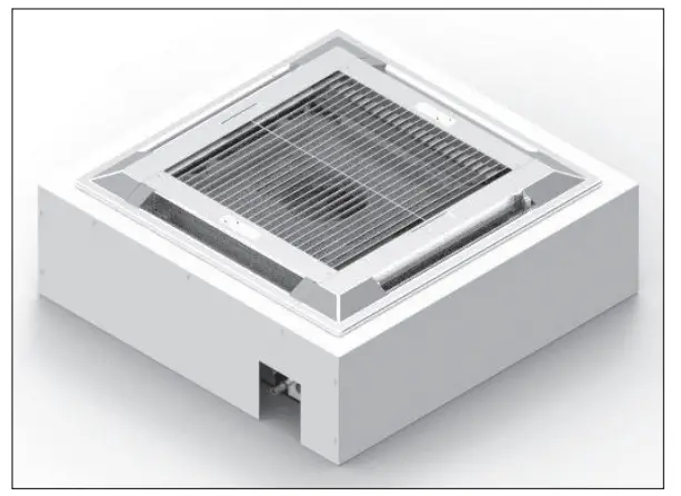
Control Valves
For control of chilled water or hot water flow, a three-way, three port diverting type valve or a two-way, two-port control valve is supplied loose for on site installation. Actuation is via a 24V signal from the unit’s electrical panel.
- Two Position Spring Return Control Valves
- Two Position Spring Return Control Valves with Two Shut Off Valves (package)
On a four pipe system where two-way valves are specified, the chilled water valve will be a normally closed type. The hot water valve will be a normally open type. Where three-way valves are specified, the same type valve will be supplied for both coils and
should be installed normally closed to the coil in the case of the chilled water coil and normally open to the coil in the case of the hot water coil.
On a two pipe changeover system where a two-way valve is specified, a normally open valve is supplied. Where a three-way valve is specified, this should be installed normally open to the coil. In both cases, a pipe mounted changeover thermostat is factory supplied and shipped loose for field installation.
The changeover thermostat is used to monitor water supply temperature and allow action of the valve accordingly.
Condensing Unit (for DX or Heat Pump units) Refer to Breeze submittal for details.
Low Ambient Kit (Use with Condensing Units)
Fan speed control for compressor operation down to 0°F outside temperature.
PERFORMANCE DATA
Table 7.1 – Cooling Performance – DX Cooling Only and Heat Pump Units
| Model | Entering Air DB °F © 50% RH |
Fan Speed | |||||
| High | Medium | Low | |||||
| Total Cooling BTU/h | Sensible Cooling BTU/h | Total Cooling BTU/h | Sensible Cooling BTU/h | Total Cooling BTU/h | Sensible Cooling BTU/h | ||
| 72 | 16,500 | 14,400 | 16,300 | 13,900 | 15,800 | 13,100 | |
| CSD/CSH 18 | 75 | 17,500 | 14,900 | 17,200 | 14,400 | 16,800 | 13,500 |
| 80 | 19,200 | 15,600 | 18,900 | 15,100 | 18,500 | 14,200 | |
| 72 | 20,000 | 16,800 | 19,600 | 16,100 | 19,300 | 15,600 | |
| CSD/CSH 24 | 75 | 21,000 | 17,300 | 20,600 | 16,500 | 20,400 | 16,000 |
| 80 | 23,000 | 18,000 | 22,600 | 17,200 | 22,200 | 16,700 | |
| 72 | 27,600 | 25,000 | 27,000 | 23,600 | 26,400 | 22,200 | |
| CSD/CSH 30 | 75 | 29,000 | 25,800 | 27,600 | 25,000 | 27,800 | 22,800 |
| 80 | 31,400 | 27,000 | 31,000 | 25,400 | 30,200 | 23,800 | |
| 72 | 33,400 | 28,400 | 33,000 | 27,600 | 32,200 | 26,200 | |
| CSD/CSH 36 | 75 | 35,000 | 29,200 | 34,600 | 28,200 | 34,000 | 26,800 |
| 80 | 38,200 | 30,400 | 37,800 | 29,400 | 37,000 | 27,800 | |
| 72 | 37,800 | 31,600 | 37,200 | 30,200 | 36,800 | 29,400 | |
| CSD/CSH 42 | 75 | 39,500 | 32,400 | 39,000 | 31,000 | 38,500 | 30,000 |
| 80 | 42,500 | 33,400 | 42,000 | 32,000 | 41,500 | 31,000 | |
Table 7.2 – Heating Performance – Heat Pump Units
| Model | Entering Air | Fan Speed | ||
| High | Medium | Low | ||
| Total Heating (BTU/h) | Total Heating (BTU/h) | Total Heating (BTU/h) | ||
| 50 | 19,100 | 18,900 | 18,600 | |
| CSH 18 | 60 | 17,800 | 17,600 | 17,200 |
| 70 | 16,400 | 16,200 | 16,000 | |
| 50 | 24,400 | 24,000 | 23,800 | |
| CSH 24 | 60 | 22,800 | 22,600 | 22,200 |
| 70 | 21,400 | 21,000 | 20,800 | |
| 50 | 30,400 | 30,200 | 29,800 | |
| CSH 30 | 60 | 29,000 | 28,800 | 28,200 |
| 70 | 27,400 | 27,200 | 26,800 | |
| 50 | 35,800 | 35,600 | 35,000 | |
| CSH 36 | 60 | 34,200 | 33,800 | 33,400 |
| 70 | 32,400 | 32,000 | 31,600 | |
| 50 | 39,500 | 39,000 | 39,000 | |
| CSH 42 | 60 | 38,200 | 37,800 | 37,800 |
| 70 | 37,200 | 36,800 | 36,600 | |
Table 8.1 – Cooling Performance – Chilled Water Units
| Model | Filter | Entering Air DB °F @ 50% RH | Chilled Water Inlet / Outlet, °F | |||||||
| 40/50°F | 45/55°F | |||||||||
| TC | SC | FLOW | PR DROP | TC | SC | FLOW | PR DROP | |||
| BTUH | BTUH | GPM | PSI | BTUH | BTUH | GPM | PSI | |||
| CCW 08 | STD. | 72 75 80 |
5,900 7,300 9,900 |
4,900 5,500 6,500 |
1.2 1.5 2.0 |
2.9 4.3 7.4 |
4,100 ,100 7,800 |
3,900 4,500 5,500 |
0.8 1.0 1.6 |
1.5 2.2 4.8 |
| MERV 10 | 72 75 80 |
4,000 5,000 6,800 |
3,300 3,700 4,400 |
0.8 1.0 1.3 |
1.6 2.3 3.8 |
2,800 3,500 5,400 |
2,600 3,100 3,700 |
0.6 0.7 1.1 |
0.8 1.2 2.5 |
|
| CW 12 | STD. | 72 75 80 |
8,800 10,900 14,600 |
7,100 8,000 9,400 |
1.7 2.2 2.9 |
1.7 2.5 4.2 |
6,100 7,600 11,200 |
5,700 6,600 8,000 |
1.2 1.5 2.2 |
0.9 1.3 2.6 |
| MERV 10 | 72 75 80 |
5,300 6,600 8,900 |
4,300 4,800 5,700 |
1.1 1.3 1.8 |
0.7 1.1 1.8 |
3,700 4,600 6,800 |
3,400 3,900 4,800 |
0.7 0.9 1.4 |
0.3 0.5 1.1 |
|
| CW 18 | STD. | 72 75 80 |
14,200 17,700 23,900 |
11,700 13,200 15,600 |
2.8 3.5 4.8 |
1.5 2.2 3.7 |
10,000 12,500 18,200 |
9,500 10,800 13,200 |
2.0 2.5 3.6 |
0.8 1.2 2.3 |
| MERV 10 | 72 75 80 |
12,900 16,000 21,600 |
10,500 11,900 14,000 |
2.6 3.2 4.3 |
1.3 1.8 3.1 |
9,000 11,300 16,500 |
8,500 9,800 11,900 |
1.8 2.3 3.3 |
0.7 1.0 1.9 |
|
| CCW 20 | STD. | 72 75 80 |
14,500 18,100 24,500 |
12,000 13,500 15,900 |
2.9 3.6 4.9 |
1.6 2.3 3.9 |
10,200 12,800 18,600 |
9,700 11,100 13,500 |
2.0 2.5 3.7 |
0.8 1.2 2.4 |
| MERV 10 | 72 75 80 |
12,900 16,000 21,600 |
10,500 11,900 14,000 |
2.6 3.2 4.3 |
1.3 1.8 3.1 |
9,000 11,300 16,500 |
8,500 9,800 11,900 |
1.8 2.3 3.3 |
0.7 1.0 1.9 |
|
| CCW 33 | STD. | 72 75 80 |
24,400 30,000 40,300 |
19,400 21,800 25,800 |
4.9 6.0 8.0 |
3.1 4.4 7.4 |
17,200 21,400 31,100 |
15,800 18,000 21,900 |
3.4 4.3 6.2 |
1.6 2.4 4.6 |
| MERV 10 | 72 75 80 |
23,300 28,700 38,400 |
18,500 20,800 24,600 |
4.6 5.7 7.7 |
2.8 4.1 6.8 |
16,400 20,500 29,700 |
15,100 17,100 20,800 |
3.3 4.1 5.9 |
1.5 2.2 4.2 |
|
| CCW 36 |
STD. |
72 75 80 |
26,800 33,100 44,600 |
21,500 24,100 28,600 |
5.3 6.6 8.9 |
3.6 5.2 8.8 |
18,900 23,500 34,300 |
17,500 19,900 24,200 |
3.8 4.7 6.9 |
1.9 2.8 5.5 |
| MERV 10 | 72 75 80 |
23,300 28,700 38,400 |
18,500 20,800 24,600 |
4.6 5.7 7.7 |
2.8 4.1 6.8 |
16,400 20,500 29,700 |
15,100 17,100 20,800 |
3.3 4.1 5.9 |
1.5 2.2 4.2 |
|
- Test conditions based on ANSI/AHRI Standard 440
- TC = Total Cooling Capacity
- SC = Sensible Cooling Capacity
- All duties based on 208V/1Ph/60Hz supply voltage and high fan speed except where stated otherwise
- Pressure drops are coil only, excluding valves
Table 9.1 – Heating Performance – Chilled Water Units with Optional Heating Coil
|
Model |
Filter |
Hot Water 180°F Inlet / 160°F Outlet | ||||||||
| 70°F Entering Air DB | 60°F Entering Air DB | 50°F Entering Air DB | ||||||||
| Capacity (btuh) | PD (psi) | Flow (gpm) | Capacity (btuh) | PD (psi) | Flow (gpm) | Capacity (btuh) | PD (psi) | Flow (gpm) | ||
|
CCW 08 |
STD. | 17,100 | 2.8 | 1.7 | 18,900 | 3.3 | 1.9 | 20,600 | 3.8 | 2.0 |
| MERV 10 | 13,400 | 1.8 | 1.3 | 14,700 | 2.1 | 1.5 | 16,100 | 2.5 | 1.6 | |
| CCW 12 | N/A | N/A | N/A | N/A | ||||||
|
CCW 18 |
STD. | 27,300 | 1.1 | 2.7 | 30,000 | 1.3 | 3.0 | 32,800 | 1.5 | 3.3 |
| MERV 10 | 24,800 | 0.9 | 2.5 | 27,300 | 1.1 | 2.7 | 29,800 | 1.3 | 3.0 | |
|
CCW 20 |
STD. | 27,900 | 1.1 | 2.8 | 30,700 | 1.4 | 3.1 | 33,500 | 1.6 | 3.3 |
| MERV 10 | 24,800 | 0.9 | 2.5 | 27,300 | 1.1 | 2.7 | 29,800 | 1.3 | 3.0 | |
|
CCW 33 |
STD. | 41,200 | 1.4 | 4.1 | 45,300 | 1.7 | 4.5 | 49,400 | 2.0 | 4.9 |
| MERV 10 | 42,300 | 1.5 | 4.2 | 45,900 | 1.7 | 4.6 | 49,300 | 2.0 | 4.9 | |
|
CCW 36 |
STD. | 45,200 | 1.7 | 4.5 | 49,800 | 2.0 | 5.0 | 54,300 | 2.3 | 5.4 |
| MERV 10 | 42,300 | 1.5 | 4.2 | 45,900 | 1.7 | 4.6 | 49,300 | 2.0 | 4.9 | |
- All duties based on 208V/1Ph/60Hz supply voltage and high fan speed except where stated otherwise
- Pressure drops are coil only, excluding valves
| Model | Entering Air DB ºF @ 50% RH | Hot Water 180ºF Inlet / 160ºF Outlet | ||
| Heating Capacity BTU/h | Flowrate GPM | Pressure Drop PSI | ||
| 50 | 46,389 | 4.8 | 1.3 | |
| CSD/CSH 18 | 60 | 42,598 | 4.4 | 1.1 |
| 70 | 38,746 | 4.0 | 0.9 | |
| 50 | 50,279 | 5.3 | 1.5 | |
| CSD/CSH 24 | 60 | 46,153 | 4.8 | 1.2 |
| 70 | 41,993 | 4.4 | 1.0 | |
| 50 | 67,912 | 7.1 | 3.3 | |
| CSD/CSH 30 | 60 | 62,277 | 6.5 | 2.8 |
| 70 | 56,609 | 5.9 | 2.3 | |
| 50 | 71,636 | 7.5 | 3.6 | |
| CSD/CSH 36 | 60 | 65,640 | 6.9 | 3.1 |
| 70 | 59,600 | 6.2 | 2.6 | |
| 50 | 77,386 | 8.1 | 4.2 | |
| CSD/CSH 42 | 60 | 70,803 | 7.4 | 3.5 |
| 70 | 64,268 | 6.7 | 3.0 | |
- All duties based on 208V/1Ph/60Hz supply voltage and high fan speed except where stated otherwise
- Pressure drops are coil only, excluding valves
UNIT DIMENSIONAL DATA
Figure 11.1 – Dimensions – Small Chassis: CCW08 and CCW12 (in inches)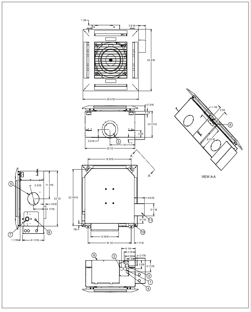
- CW OUTLET
- CW INLET
- HW INLET (Optional)
- HW OUTLET (Optional)
- BRANCH DUCT OPENING (x3)
- FRESH AIR INTAKE (x2)
- PUMP INSPECTION PORT
- CONDENSATE DRAIN
- CONTROL PANEL
- MOUNTING BRACKET
- ELECTRIC HEAT FUSE BOX OR TRANSFORMER
Figure 12.1 – Dimensions – Medium Chassis: CCW18 and CCW20 (in inches)
- CW OUTLET
- CW INLET
- HW INLET (Optional)
- HW OUTLET (Optional)
- FRESH AIR INTAKE (x3)
- BRANCH DUCT OPENING (x4)
- PUMP INSPECTION PORT8
- CONDENSATE DRAIN
- ONTROL PANEL
- OUNTING BRACKET
- ELECTRIC HEAT FUSE BOX OR TRANSFORMER
- CW OUTLET
- CW INLET
- HW INLET (Optional)
- HW OUTLET (Optional)
- FRESH AIR INTAKE (x3)
- BRANCH DUCT OPENING (x4)
- PUMP INSPECTION PORT
- CONDENSATE DRAIN
- CONTROL PANEL
- MOUNTING BRACKET
- ELECTRIC HEAT FUSE BOX OR TRANSFORMER
Figure 14.1 – Dimensions – Medium Chassis: CSD/CSH 18 and CSD/CSH 24 (in inches)
- DX LIQUID LINE
- DX SUCTION LINE
- HW INLET (Optional)
- HW OUTLET (Optional)
- FRESH AIR INTAKE (x3)
- BRANCH DUCT OPENING (x4)
- PUMP INSPECTION PORT
- CONDENSATE DRAIN
- CONTROL PANEL
- MOUNTING BRACKET
ELECTRIC HEAT FUSE BOX OR TRANSFORMER
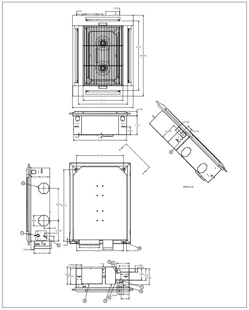
Figure 15.1 – Dimensions – Large Chassis: CSD/CSH 30, CSD/CSH 36 and CSD/CSH 42 (in inches)
- DX LIQUID LINE
- DX SUCTION LINE
- HW INLET (Optional)
- HW OUTLET (Optional)
- FRESH AIR INTAKE (x3)
- BRANCH DUCT OPENING (x4)
- PUMP INSPECTION PORT
- CONDENSATE DRAIN
- CONTROL PANEL
- MOUNTING BRACKET
- ELECTRIC HEAT FUSE BOX OR TRANSFORMER
Figure 16.1 – Technical Data – DX Cooling Only and Heat Pump Units
| Model Digit 2,3 + Model Size | |||||||
| DESCRIPTION | UNITS | SD/SH 18 | SD/SH 24 | SD/SH 30 | SD/SH 36 | SD/SH 42 | |
| CONSTRUCTION | Material: Fascia | High Impact Polystyrene (Pearl Grey color), UL94 VO Fire Rating | |||||
| Material: Chassis | Galvanized Steel | ||||||
|
EVAPORATOR |
Type | Finned Tube | |||||
| Quantity | 1 | ||||||
| Face Area | ft2 | 4.0 | 5.2 | ||||
| Nominal Airflow – H/M/L | CFM | 590 / 540 / 465 | 670 / 590 / 540 | 920 / 800 / 680 | 1000 / 920 / 800 | 1130 / 1000 / 920 | |
| Discharge | 4-Way | ||||||
|
FAN |
Type | Centrifugal | |||||
| Quantity | 1 | 2 | |||||
| Diameter | in | 14.0 | |||||
| Horsepower (per fan) | HP | 1/6 | |||||
| REFRIGERATION | Number of Circuits | 1 | |||||
| Refrigerant Type | R-410A | ||||||
| WEIGHTS | Weight – Chassis | lbs | 66 | 97 | |||
| Weight – Fascia | 18 | 21 | |||||
|
CONNECTIONS |
Suction (1) |
in |
0.75 | ||||
| Liquid (1) | 0.375 | ||||||
| Condensate (ID) | 0.375 | ||||||
|
FILTRATION |
Type | Washable Polyester Foam (Standard) | |||||
| Size | in | 11.6 x 23.2 x 0.2 | |||||
| Type | MERV 10 | ||||||
| Nominal Size | in | 12.0 x 25.0 x 1.0 | |||||
| Quantity | 2 | 3 | |||||
| CONDENSATE PUMP | Maximum Head | in | 30 | ||||
| Nominal Flowrate | gym | 0.1 | |||||
|
OPTIONS |
Electric Heating Capacity | kW | 3.0 | 5.0 | |||
| Max Supply Air Branch Duct
Connections |
qty | 2 | |||||
| Supply Air Branch Duct Diameter | in | 5.0 | 6.0 | ||||
| Ducted Supply Air Volume (2) | CFM | 115 | 130 | 180 | 200 | 220 | |
| Fresh Air Connections | qty | 3 | |||||
| Fresh Air Duct Diameter | in | 3.0 | |||||
| Fresh Air Volume (3) | CFM | 60 | 65 | 85 | 90 | 95 | |
- Refrigerant line sizes should always match condensing unit connection sizes.
- Maximum air volume available through one branch duct 6′ long, with Cassette fan(s) at high speed and corresponding fascia aperture closed.
- Maximum fresh air through all knockouts connected to one 10′ long duct with fan at high speed. Fresh air volume will depend on duct configuration, fan speed, and filter type.
- For electrical data, please refer to the submittal data in Breeze AccuSpec
.Figure 17.1 – Technical Data – Chilled Water Units
| Model Digit 2,3 + Model Size | ||||||||
| DESCRIPTION | UNITS | CW08 | CW12 | CW18 | CW20 | CW33 | CW36 | |
| CONSTRUCTION | Material: Fascia | High Impact Polystyrene (Pearl Grey color), UL94 VO Fire Rating | ||||||
| Material: Chassis | Galvanized Steel | |||||||
|
CHILLED WATER COIL |
Type | Finned Tube | ||||||
| Quantity | 1 | |||||||
| Face Area | ft2 | 1.8 | 2.8 | 5.2 | ||||
| Nominal Airflow – Standard –
H/M/L |
CFM | 330/300/260 | 360/330/300 | 600/540/460 | 620/600/540 | 940/850/740 | 1080/940/850 | |
| Nominal Airflow – MERV 10 –
H/M/L |
CFM | 200 / 170 / 160 | 520 / 490 / 450 | 880 / 760 / 690 | ||||
| Discharge | 4-Way | |||||||
| Unit Water Volume | gal | 0.29 | 0.45 | 0.79 | ||||
| Maximum Inlet Water Pressure | psi | 125 | ||||||
|
FAN |
Type | Centrifugal | ||||||
| Quantity | 1 | 2 | ||||||
| Diameter | in | 12.0 | 15.0 | 14.0 | ||||
| Horsepower (per fan) | HP | 1/8 | 1/6 | |||||
| WEIGHTS | Weight – Chassis | lbs | 40 | 64 | 97 | |||
| Weight – Fascia | 5 | 18 | 21 | |||||
|
CONNECTIONS |
Chilled Water Inlet |
in |
0.625 | 0.875 | ||||
| Chilled Water Outlet | 0.625 | 0.875 | ||||||
| Condensate (ID) | 0.375 | |||||||
|
FILTRATION |
Type | Washable Polyester Foam (Standard) | ||||||
| Size | in | 14.5 x 13.5 x 0.2 | 11.6 x 23.2 x 0.2 | |||||
| Type | MERV 10 | |||||||
| Size | in | 13.0 x 13.0 x 1.0 | 12.0 x 25.0 x 1.0 | |||||
| Quantity | 1 | 2 | 3 | |||||
| CONDENSATE PUMP | Maximum Head | in | 30.0 | |||||
| Nomincal Flowrate | GPM | 0.1 | ||||||
|
OPTIONS |
Electric Heating Capacity | kW | 1.5 | 3.0 | 5.0 | |||
| Max Supply Air Branch Duct Connections | qty | 2 | ||||||
| Supply Air Branch Duct Diameter | in | 5.0 | 6.0 | |||||
| Ducted Supply Air Volume (1) | CFM | 80 | 100 | 125 | 200 | 220 | ||
| Fresh Air Connections | qty | 2 | 3 | |||||
| Fresh Air Duct Diameter | in | 3.0 | ||||||
| Fresh Air Volume (2) | CFM | 40 | 60 | 65 | 90 | 95 | ||
THIS PAGE INTENTIONALLY LEFT BLANK
Ceiling Cassette
Modine Manufacturing Company
1500 De Keven Avenue
Racine, Wisconsin 53403-2552
Phone: 1.866.823.1631
www.modinehvac.com
©2023 Modine Manufacturing Co.
Follow us @ModineHVAC
See us at YouTube.com/ModineHVAC
www.linkedin.com/company/modinehvac/