![]()
N2 Qual. Particle FOUP
Product Specification
(December, 2019)
PLUTO SOLUTION
The material contained in this product specification is proprietary to the PLUTOSOLUTION and may be subject to legal punishment if it is reproduced and used without permission. There may be some differences between the product image and the physical presence contained in the specification.
Contents
Introduction of the product
‘FOUP’ is designed to check the gas flow into the FOUP. Quantity measurements by dust size, flow measurements by pass among N2 GAS entering FOUP, and FOUP settling LEVEL measurements are collected and forwarded to the server.
Composition of the product
Particle FOUP
ADB Cable
12.6V 13.6A Lithium-ion battery pack
12.6V 4A charger
| Division | Model | Quantity (EA) | Remarks | |
| Particle FOUP | FOUP | Particle FOUP | 1 | Battery pack included |
| Accessory | ADB Cable | 1 | ||
| 12.6V 4A Charger | 1 | For charging the battery pack | ||
| 12.6V 13.6A Lithium-ion battery pack | 1 | |||
Main Product Information
3.1. Particle FOUP
3.1.1. External Appearance
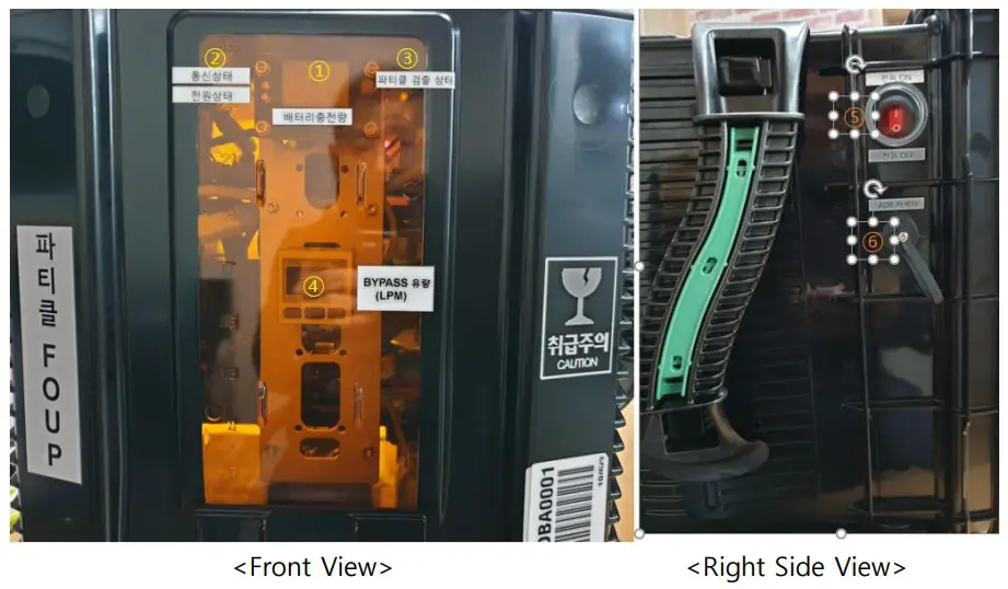
| Location | Designation |
| ① | Battery charge indicator |
| ② | Status LED – Network, Power |
| ③ | Status LED – Particle detection |
| ④ | Flow sensor monitor (Bypass Flow) |
| ⑤ | Power switch |
| ⑥ | ADB connector (Wired charging port – 24V 6.25A Power adapter connection) |
3.1.2. Interior
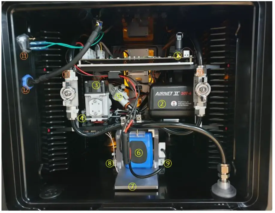
| Location | Details |
| ① | IoT module (Main Board) |
| ② | Particle counter |
| ③ | Vacuum pump |
| ④ | Flow sensor |
| ⑤ | Speed Controller |
| ⑥ | 12.6V 13.6A Lithium-ion battery pack |
| ⑦ | Wireless Charging RX Coil Mount |
| ⑧ | Magnetic switch |
| ⑨ | Magnetic |
| ⑩ | Finger Valve (Rear1, Rear2) |
| ⑪ | Power switch |
| ⑫ | ADB connector (Wired charging port – 24V 6.25A Power adapter connection) |
3.1.3. Product specification
| Division | Main specifications |
| IoT Platform | ARM® Cortex™-A53 Quad Core 1800MHz LP-DDR4 1024MB / eMMC 8GB |
| Wireless | Wi-Fi 802.11 ac/a/b/g/n |
| Power | 12.6V / 13,600mAh Lithium-ion Battery Pack (Connecting connector: Molex 5557-04R) |
| Display | Power state LED : Green Communication status LED : Green Particle Detection Status LED : Green+Red Battery charge : Red 2-digit Seven Segment LED 1 x flow sensor monitor : (model name: PFM311-MLEF) |
| Sensor | Dual-Axis Digital Inclinometer and Accelerometer (ADIS16209) Particle counter (model name: Airnet II 201 with 24VDC) 1 x flow sensor (model name: PFM525-C6-2-R) |
| Vacuum pump | 1 x vacuum pump (model name: DP0102S) |
| I/F | 1 x power switch 1 x ADB connector |
| Operating temperature range |
0 ℃ ~ 50 ℃ |
| Weight | Entegris Particle FOUP: 8.44 Kg Miraial Particle FOUP: 8.61 Kg |
3.2. Board Specification
3.2.1. IoT module (Main Board)
3.2.1.1. Appearance
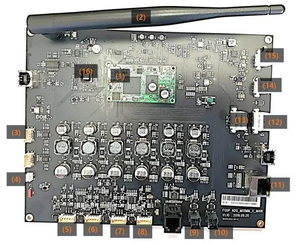
| Location | Designation |
| (1) | iMX8M Mini SOM (System On Module) |
| (2) | WiFi 5GHz Antenna |
| (3) | Indicator Board Connection Connector (I2C) |
| (4) | Magnetic Switch Connection Connector |
| (5) | Flow sensor Connection Connector (Power + signal) |
| (8) | N/A |
| (9) | Particle sensor power Connector |
| (10) | Vacuum pump power Connector |
| (11) | Particle Sensor Connection Connector (Ethernet for data) |
| (12) | Wireless / wired charging Rx Board Connection Connector |
| (13) | External power + ADB to USB Connection Connector |
| (14) | Power switch connection Connector |
| (15) | Connect the rechargeable battery pack Connector |
| (16) | 2-axis digital angle and accelerometer |
3.2.1.2. Product specification
| Location | Designation |
| IoT Platform | ARM® Cortex™-A53 Quad Core 1800MHz LP-DDR4 1024MB / eMMC 8GB |
| Wireless | Wi-Fi 802.11 ac/a/b/g/n |
| Power | 12.6V / 13,600mAh Lithium-ion Battery Pack (Connecting connector: Molex 5557-04R) |
| Sensor | Dual-Axis Digital Inclinometer and Accelerometer (ADIS16209) |
| I/F | 1 x Indictor Board connection port (Connection Connector: 35507-0400) 1 x Magnetic Switch connection port (Connection Connector: PHR-2) 1 x flow sensor connection ports (Connection Connector: 35507-0500) 1 x particle sensor power connection port (172256-1002) 1 x vacuum pump power connection port (172256-1002) 1 x connection port for particle sensor data (RJ45) 1 x wireless / wired charging Rx Board connection port (Connection Connector: 5557-6R) External power + 1 x ADB to USB connection port (Connection Connector: 5557-6R) 1 x power switch connection port (Connection Connector: 5557-04R) 1 x rechargeable battery pack connection port (Connection Connector: 5557-04R) |
| Operating temperature range |
0 ℃ ~ 50 ℃ |
| Weight | 265.5 g |
| Size | W200 x d160 x h20 mm (Antenna exclusion height) |
3.2.2. Indicator Board
3.2.2.1. Appearance

| Location | Designation |
| (1) | Battery level indicator (2-Digit Seven Segment LED) |
| (2) | Communication status display LED (Green) |
| (3) | Power status indicator LED (Green) |
| (4) | Particle Status Display LED (Green+Red) |
| (5) | Main Board Connection Connector (I2C) |
3.2.2.2. Product specification
| Division | Main specifications |
| Battery level indicator | Red 2-Digit Seven Segment LED Battery voltage % display (10, 20, ~, 90, 99:FULL) “Voltage” and “LL” cross indications below 30% |
| Communication status LED | Green LED Blink when trying to connect to WiFi, On when transmitting data |
| Power Status Indicator LED | Green LED On when power is applied |
| Particle Status LED | Red-Green LED Red Blink on Particle Sensor Error Red On when detecting particles Undetected Particles Green On |
| POWER | 3.3V (Power supply from main board) |
| I/F | 1 x main board connection port (Connection Connector: 35507-0400) |
| Operating temperature range | 0 ℃ ~ 50 ℃ |
| Weight | 10.5g |
| Size | w50 x d30 x h23 mm |
3.2.3. Wireless / Wired Charge Rx Board
3.2.3.1. Appearance

| Location | Designation |
| (1) | Main Board Connection Connector |
| (2) | Ferrite Plate |
| (3) | Coil |
| (4) | Lead Wire |
3.2.3.2. Product specification
| Division | Main specifications |
| Wired / wireless charging | Input power : 24V / 6.5A (Adapter Specification) Output power : 12.6V / 4A |
| I/F | 1 x main board connection port (Connection Connector: 5569-06A2) 1 x Magnetic Switch connection port (Connection Connector : 5264-02) |
| Operating temperature range | 0 ℃ ~ 50 ℃ |
| Weight | 156g (Rx Coil Included) |
| Size | Rx Board : w100 x d90 x h20 mm (Heat sink Included) Rx Coil : w70 x d60 x h6.9 mm (Ferrite Plate Included) |
3.3. Sensor & Pump Specifications
3.3.4. Flow sensor
3.3.4.1. Appearance

3.3.4.2. Product specification
| Division | Main specifications |
| Model name | PFM525-C6-2-R |
| Applicable fluid | Dry air, N2, Ar, CO2 |
| Flow rate range | 0.5 to 25 L/min |
| Accuracy | ±3% F.S. or less |
| Repeatability | ±5% F.S. or less (base on 0.35 MPa) |
| Operating pressure range | -100 kPa to 750 kPa |
| Rated pressure range | -70 kPa to 750 kPa |
| Proof pressure | 1 MPa |
| Analog output | Response time : 1 sec Current output: 4 to 20 mA |
| Power supply voltage | 24 VDC ±10% |
| Operating temperature range | 0 to 50oC |
| Size | w64.6 x h43 x d18 (mm) |
| Weight | 55 g |
3.3.5. Flow sensor monitor
3.3.5.1. Appearance

3.3.5.2. Product specification
| Division | Main specifications |
| Model name | PFM311-MLEF |
| Applicable Sensor | PFM525 |
| Instantaneous flow | Display flow range : 0.5 to 26.3 L/min Min. setting/display unit : 0.1 L/min |
| Accumulated flow | Setting / display flow range : 0 to 1999999 L Min. setting /display flow unit : 1 L |
| Accumulated flow volume per pulse | 0.1 L/Pulse |
| Display Unit | Instantaneous flow : L/min, CRM x 10-2 Accumulated flow : L, ft3 x 10-1 |
| Analog output | Output current : 4 to 20 mA Response time : 1.5 sec Accuracy : ±1% F.S. max. |
| Sensor Input | Current input : 4 to 20 mA |
| Repeatability | ±0.1% F.S. max. (Fluid : Dry air) Analogue output accuracy : ±0.3% F.S. max. |
| Display accuracy | ±0.5% F.S. ±1digit max. |
| Power supply voltage | 24 VDC ±10% |
| Operating temperature range | 0 to 50oC |
| Size | w30 x h30 x d35.7 (mm) |
| Weight | 30 g |
3.3.6. Particle counter
3.3.6.1. Appearance

3.3.6.2. Product specification
| Division | Main specifications |
| Model name | Airnet II with 24VDC (201-4) |
| Size range (μm) | 0.2, 0.3, 0.5, 1.0 |
| Flow rate | 0.1 CFM (2.8 LPM) |
| Counting efficiency | 50% ±20% for most sensitive channel 100% ±10% at 1.5 to 2.0 times channel one size |
| Zero count | ≤ 70.7 counts/m3 |
| Max. concentration | 5,057,310 /ft3 |
| Laser source | Diode / Class 1 per EN60825) |
| Flow system | External vacuum 1/4” connection |
| Power supply voltage | 24 VDC 0.5A |
| Operating temperature range | 4 to 35oC |
| Size | W135 x h890 x d960 (mm) |
| Weight | 630 g |
3.3.7 Vacuum pump
3.3.7.1. Appearance

3.3.7.2. Product specification
| Division | Main specifications |
| Model name | DP0102S |
| Attainable vacuum | -26.7 kPa |
| Free air displacement | 7.0 L/min |
| Working pressure range | -26.7 kPa to 45 kPa |
| Rated performance | 5,000 hours |
| Max. concentration | 5,057,310 /ft3 |
| Rated voltage | 24 VDC (Max. current: 0.5A) |
| Operating temperature range | 4 to 35oC |
| Size | 50 (L) x 30 (W) (mm) |
| Weight | 250 g |
Precautions
- Make sure to use connectors and cables that match the connection terminals. Using a connector other than the dedicated connector may cause product malfunction or failure.
- Secure the unit firmly where you want to install it.
- Do not install in water or rainwater spatter or damp areas.
- Be careful not to introduce moisture or other foreign substances into the product.
- Be careful not to drop the product or give an external shock.
- Do not disassemble, modify, or alter the product arbitrarily.
- This product is designed for use in the temperature range of 0 ° C to 50 °C. Outside this range, use at extremely low or high temperatures is undesirable.
- Do not install or use the product outside of its intended purpose.
- If there is a burning smell during operation, immediately turn off the power and contact the PLUTOSOLUTION Customer Support Center (031-3376780)
※ FCC
This device complies with part 15 of the FCC Rules. Operation is subject to the following two conditions: (1) This device may not cause harmful interference, and (2) this device must accept any interference received, including interference that may cause undesired operation.
Any changes or modifications (including the antennas) to this device that are not expressly approved by the manufacturer may void the user’s authority to operate the equipment.
Note :
This equipment has been tested and found to comply with the limits for a Class A digital device , pursuant to part 15 of the FCC Rules. These limits are designed to provide reasonable protection against harmful interference in a residential installation . This equipment generates, uses and can radiate radio frequency energy and, if not installed and used in accordance with the instructions , may cause harmful interference to radio communications. However, there is no guarantee that interference will not occur in a particular installation . If this equipment does cause harmful interference to radio or television reception , which can be determined by turning the equipment off and on, the user is encouraged to try to correct the interference by one or more of the following measures:
- Reorient or relocate the receiving antenna.
- Increase the separation between the equipment and receiver.
- Connect the equipment into an outlet on a circuit different from that to which the receiver is connected.
- Consult the dealer or an experienced radio/TV technician for help.
✓ This device is installed inside the facility.
This device is used at a distance of more than 20cm from the human body.
※ RF Exposure Statement
FCC RF Radiation Exposure Statement: This equipment complies with FCC RF Radiation exposure limits set forth for an uncontrolled environment.
This device and its antenna must not be co-located or operating in conjunction with any other antenna or transmitter..
![]()